Table of Contents
Advertisement
COMINOX
Via G. Viganò, 7
20048 CARATE BRIANZA
Milano (Italy)
Phone: +39 0362.91.23.12
Fax: +39 0362.90.09.40
www.cominox.com
e-mail: carlo.torti@cominox.it
Mod.
18 S
18 B
18 BHD
The present operating instructions ARE NOT integral to the unit. The instructions
are only to be supplied to qualified and specialised technicians liable to ordinary
service and unit repairing. Technicians or operators liable for the unit installations
are to be authorised in writing by COMINOX.
Any operator or technician is liable to read the operating instructions and strictly
comply with its instructions and information as COMINOX is not liable at all for any
damage to people or things or to the unit, should the operator not comply with the
hereby described general operating conditions.
Such instructions are confidential and the customer is liable not to disclose any
information. What is more such operating instructions and its annexes can not be
changed, tampered, modified, violated, copied or sold anybody without COMINOX
SERVICE MANUAL
24 BHD
FOREWORD
approval.
SERVICE MANUAL
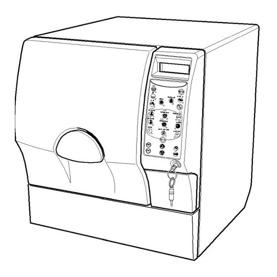
AUTOCLAVE
Sterilising
STERILCLAVE 18/24
Document Code: SCG04824
Mod.
24 S
24 B
S
1
Page:
Advertisement
Table of Contents

Related Manuals for COMINOX STERILCLAVE 18 Series


Summary of Contents for COMINOX STERILCLAVE 18 Series
-
Page 1: Foreword
Any operator or technician is liable to read the operating instructions and strictly comply with its instructions and information as COMINOX is not liable at all for any damage to people or things or to the unit, should the operator not comply with the hereby described general operating conditions. -
Page 2: Table Of Contents
SERVICE MANUAL Page: INDEX FOREWORD ...................... 1 INDEX ........................ 2 Reference numerical index ............. 3 Reference alphabetical index ............3 SIGNALLING ..................... 5 Cooling Stop ................... 5 Check water quality ................ 6 Check automatic filling ..............6 Waste water maximum level ............7 Open door or door not locked ............ -
Page 3: Reference Numerical Index
SERVICE MANUAL Page: Reference numerical index 03, power supply cable .................. 8, 16 05, metering funnel ....................9 06, access keys ..................... 5, 22 08, tray holder ...................... 9 09, chamber ..............5, 9, 10, 11, 12, 14, 17 10, clean water tank ..............9, 10, 18, 28, 29 11, waste water recovery tank ............ - Page 4 SERVICE MANUAL Page: direct waste drain 30 ..................7, 18 dirty water drain tap 25 ................7, 28, 29 door 16 ................... 5, 7, 9, 11, 13, 16 drain filter 20 ....................13, 17 fans 42 ................... 11, 13, 26, 27 filler 14 .....................
-
Page 5: Signalling
SERVICE MANUAL Page: SIGNALLING Signals and signalling are messages which in the majority of cases ask for a simple correction or control operation by the user. Alarms ask for service or informs about the presence of a possible failure. When enabled, they are displayed on the display, followed by a sound running for 30 seconds. -
Page 6: Check Water Quality
SERVICE MANUAL Page: Check water quality CHECK WATER QUALITY Such a signalling is only present on any model fitted with a water demineralisation unit (OPTIONAL). Under such conditions, the unit is fitted with a conductivity meter on water coming from the demineralisation system. Such a signalling is released during STAND-BY, only when the unit is fitted with the optional demineralisation unit and the water self drain 29 is programmed, in the B configuration from the water system (refer to the OPERATING AND... -
Page 7: Waste Water Maximum Level
SERVICE MANUAL Page: Waste water maximum level WASTE WATER MAXIMUM LEVEL It signals that the waste water recovery tank 11 is full and must be emptied. The signal is released at the cycle start-up. Empty the tank (refer back to OPERATING AND SERVICE INSTRUCTIONS, chapter INSTALLATION, description TANK SELF DRAIN). -
Page 8: Manual Stop Alarm
SERVICE MANUAL Page: Manual stop alarm MANUAL STOP ALARM It signals that during the cycle start-up, the STOP key was pressed before the natu- ral cycle conclusion. The signal is released during operation and the unit is stopped to inform the user that the load is NOT STERILE. -
Page 9: Alarms
SERVICE MANUAL Page: ALARMS Differently from any signal, alarm STOP the unit, therefore once solved the problem which provoked the alarm and reset the alarm itself pressing the key STOP, it is necessary to switch the unit ON once more and the start a new cycle. The load in the autoclave during the cycle interrupted by the alarm is to be consid- ered NON STERILE. -
Page 10: Poor Water Quality
SERVICE MANUAL Page: Poor water quality POOR WATER QUALITY Such an alarm is present only on unit where a water demineralisation unit is fitted (OPTIONAL). Under such conditions, the unit is fitted with a conductivity meter of the water coming from the demineralisation unit. Under such conditions, the unit signals that the water conductivity level overcame an acceptable level and stops the automatic filling. -
Page 11: Triac Alarm
SERVICE MANUAL Page: TRIAC alarm TRIAC ALARM Such an alarm informs about the safety thermostat operation 17. The alarm is displayed on the unit when the circuit on the coils IS NOT closed. The following controls and checks are to be enforced in the specified order: Reset the safety thermostat 17 , removing its cap and pressing the pin under it. -
Page 12: Pressurisation Alarm
SERVICE MANUAL Page: Replace it when overcoming the fixed schedule on the PROGRAMMED SERVICE TABLE (refer back to the OPERATING and SERVICE INSTRUCTIONS, chapter SERVICE). Any possible cleaning is to be enforced as follows: - remove the solenoid valve, minding the specific part sequence, to re-assemble it when required (A) - clean the valve core (B) as to allow the tight seal to correctly slide inside, pushed by the small spring (C). -
Page 13: Insufficient Vacuum Alarm
SERVICE MANUAL Page: Insufficient vacuum alarm INSUFFICIENT VACUUM ALARM The alarm signals that during the pre-vacuum phase, pressure did not reach the correct set value. The alarm is displayed during a cycle, in the pre-vacuum phase, when pres- sure did not reached the correct programmed value. Check the efficiency and cleaning of the chamber seal 31 and on the door 16 internal disk, which it is fitted against and possibly, if damaged, replace it. -
Page 14: Over-Temperature Sterilisation Temperature Band
SERVICE MANUAL Page: Over-temperature sterilisation temperature band OVER-TEMPERATURE STERILISATION TEMP. STER. Under-temperature sterilisation temperature band Both alarms signal that there is no longer compliance with the sterilisation tempera- UNDER-TEMPERATURE ture band. The sterilisation temperature band (tolerance) is defined by the regula- STERILISATION TEMP. -
Page 15: Lost Data Alarm
SERVICE MANUAL Page: Lost data alarm LOST DATA ALARM Such an alarm signals a data loss from the RAM memory (refer back to DIAGRAMS and WIRINGS, logic electronic motherboard). One of the main reasons the data loss depends on is the wrong assembly of the RAM or EPROM memories Check that some pins on the memory is not broken, folded or out of its correct seat... -
Page 16: Controls Or Additional Adjusting
SERVICE MANUAL Page: CONTROLS OR ADDITIONAL ADJUSTING ........Empty or not-well readable display If no information is displayed on the display and/or any displayed information is not well visible, mainly check what follows: Check power at the socket level, the correct fitting of the power supply cable 03 into the supply socket and its connection to the unit. -
Page 17: Water In The Tank After The Cycle
SERVICE MANUAL Page: Water in the tank after the cycle If at the end of the cycle, there is still water inside the chamber 09 it is necessary to follow the hereby described procedure: Check that the selected cycle includes drying, otherwise it is nor- mal that there is still some water or moist inside the chamber. -
Page 18: Vacuum Pump
SERVICE MANUAL Page: Vacuum Pump The vacuum pump can be checked by simply cleaning it or replacing its seals, sup- plied in kit. More precisely in the case of the vacuum pump 41 A, it is necessary to check what follows: Remove the pump, attentively checking the part position;... -
Page 19: The Printer Does Not Print
SERVICE MANUAL Page: Fit the external filling and drain pipes; the filling pipe in the terminal portion is custom cut to avoid the sucker effect when on the tank bottom; the drain pipe is fitted with a male rapid connecting joint. Check the unit and its tightness;... - Page 20 SERVICE MANUAL Page: must be directed with its components turned towards the machine inside; of the two connectors, the one with 2 PIN must be placed in the upper part and the one with 4 PIN in the lower part; On the 2 PIN connector, link the connector (T) of the cable already pre- mounted on the wiring aboard the machine;...
-
Page 21: Water Automatic Drain Does Not Work
SERVICE MANUAL Page: Water automatic drain does not work If the water self drain 29 (OPTIONAL) does not perfectly work, it is necessary to follow the hereby described proce- dure: As not all the models are fitted with an automatic drain, check that such a function is available on the existing unit;... -
Page 22: Diagrams And Wirings
SERVICE MANUAL Page: DIAGRAMS AND WIRINGS Logic electronic motherboard The logic motherboard 33 is a low tension motherboard, the same on each unit. It is supplied with no memory: EPROM and RAM, as it is necessary to use the customer memories. -
Page 23: Logic Motherboard Electric Wiring 33
SERVICE MANUAL Page: Logic motherboard electric wiring 33... -
Page 24: Power Electronic Motherboard
SERVICE MANUAL Page: Power electronic motherboard The power electronic motherboard 34 is the same on any unit model. ON-OFF Remote control switch and cut-out switch Fuse to protect the power motherboard supply (T250 Volts delayed 250 mA); Fuse to protect the transformer, additional circuit (T250 Volts delayed 630 mA);... -
Page 25: Power Motherboard Electric Wiring 34
SERVICE MANUAL Page: Power motherboard electric wiring 34... -
Page 26: Electric Wiring 18S - B - Bhd / 24S - B
SERVICE MANUAL Page: Electric wiring 18S - B - BHD / 24S - B - EV… solenoid valves - P1 water drain pump 35 door blocking coil - P2 water self charge pump 46 (configuration A) - CT1 power contactor Solenoid valve EV7 (configuration B) - CT2 resistance piloting contactor... -
Page 27: Electric Wiring 24Bhd
SERVICE MANUAL Page: Electric wiring 24BHD - EV… solenoid valves - P1 water drain pump 35 door blocking coil - P2 water self charge pump 46 (configuration A) - CT1 power contactor Solenoid valve EV7 (configuration B) - CT2 resistance piloting contactor - PR safety pressure switch vacuum pump 41... -
Page 28: Hydraulic Wiring 18S - B - Bhd / 24S - B
SERVICE MANUAL Page: Hydraulic wiring 18S - B - BHD / 24S - B - EV… solenoid valves - RS1 clean water drain tap 24 door blocking coil - RS2 dirty water drain tap 25 air sterilisation filter 15 - RDS direct drain (only on model BHD) water drain pump 35 clean water tank 10... -
Page 29: Hydraulic Diagram 24 Bhd
SERVICE MANUAL Page: Hydraulic diagram 24 BHD - EV… solenoid valves - RS1 clean water drain tap 24 door blocking coil - RS2 dirty water drain tap 25 air sterilisation filter 15 - RDS direct drain (only on model BHD) - P1 water drain pump 35 - SC...
Need help?
Do you have a question about the STERILCLAVE 18 Series and is the answer not in the manual?
Questions and answers
We face alaram pressurization What can we do for this
To address pressurization alarm issues with the COMINOX STERILCLAVE 18 Series:
1. Follow the instructions in the INSUFFICIENT STEAM ALARM solution.
2. If the alarm persists, check for faults in the heating circuit.
3. During pressurisation or steam peaks, ensure the chamber internal coil is correctly powered (refer to wiring diagrams).
4. Replace chamber probe 21 if necessary.
This answer is automatically generated
how can I unblock the door