
Related Manuals for Nitto Seiko FF/FM311DR


Summary of Contents for Nitto Seiko FF/FM311DR
- Page 1 Compact Drum Type Screw Feeder FF/FM311DR Instruction Manual version (For system 02.00) FF311DR type Assembly Machine Division...
- Page 2 Nitto Seiko Co., Ltd. (2)By provision of operating manual recorded on CD-ROM, you shall be deemed to have agreed to the Terms and Conditions written in “readme.txt” on it.
- Page 3 Preface Thank you very much for your purchase of Compact drum type screw feeder “FF/FM311DR” (hereafter called “FF/FM311DR”). This FF/FM311DR screw feeder, allowing optimal alignment and feeding of screws depending on the type of screws, has characteristics shown below. (1) It is applicable to main commercial supply voltage used worldwide.
- Page 4 If any fault, including fume, abnormal odor and noise, is found in the machine, turn off the power switch first, then shut down the power supplied, and ask sales agent or your nearest sales office of Nitto Seiko Co., Ltd. for repair. Use of the faulty machine without repair may cause fires, electric shocks, or accidents.
- Page 5 WARNING Satisfy the conditions required for the operating environment. Otherwise, fires, electric shock, or faults may occur. Use this product at a 1000 m or less height in ordinary indoor environment, satisfying the conditions shown below. Free from corrosive or flammable gas The atmosphere is free from conductive powder, including iron powder.
- Page 6 ! CAUTION CAUTION DO NOT touch any of moving parts while the machine is running. Otherwise, injuries or malfunctions may occur. CAUTION Always use the connecting cables specified by us. When handing them, pay extreme attention. Carefully lay connecting cables to prevent them from being caught by your foot or pinched by a heavy object placed on it.
-
Page 7: Table Of Contents
Contents Outline of FF/FM311DR ....................1 1.1. Features of FF/FM311DR ....................1 1.2. Structure of FF/FM311DR ....................1 Types of FF/FM311DR ..................... 2 2.1. Model ..........................2 2.2. Designations and models of connecting cables ..............2 2.3. Designations of components ..................... 3 2.3.1. - Page 8 8.2.1. Before setup ..........................22 8.2.2. Outline of operation in setup and adjustment mode ..............22 8.2.3. FF/FM311DR Setup and adjustment mode function list ............. 23 8.3. Setup and adjustment items .................... 25 8.3.1. Operation parameter setup ......................25 8.3.2.
-
Page 9: Outline Of Ff/Fm311Dr
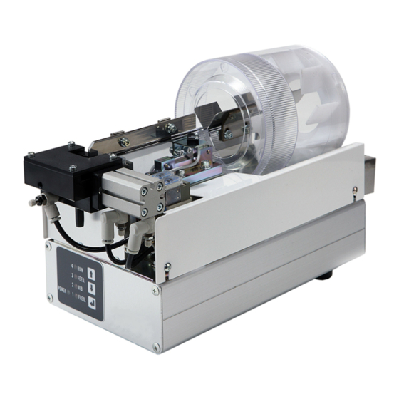
(4) Screws fed to the chuck unit by compressed air are tightened until they are screwed into works. 1.2. Structure of FF/FM311DR The main structure of FF/FM311DR is as shown in the figure below. Stepping motor Photoelectric sensor Solenoid valve... -
Page 10: Types Of Ff/Fm311Dr
2. Types of FF/FM311DR 2.1. Model Models of the FF/FM311DR are defined by substituting the specified symbols for (1) to (3) shown below. FF311DR-(1)(2)(3): Automatic type (including screw taking-out type) FM311DR-(1)(2)(3): Handheld driver type Symbols Details (1)(2) Escapement unit type... -
Page 11: Designations Of Components
2.3.2. Back face (8) Power switch (SW1) This switch turns ON/OFF the FF/FM311DR. (9) Fuse (Contained in fuse holders FU2 and FU3) 0215004. MXP made by Littelfuse (5 × 20 mm 250 VAC 4 A time lag type complying with RoHS) -
Page 12: Installation Of Ff/Fm311Dr
Installation Install the FF/FM311DR on a solid and horizontal floor (or table) so that screws can be fed from the top face, setup can be carried out from the front face, and the power switch can be operated from the back face, for correct vibration to be performed for screw alignment (see the figure shown below). -
Page 13: Preparation Of Operation
Preparation of operation Before starting operation, make preparations as follows: 4.1. Connection of screw feeding hose When connecting the screw feeding hose WARNING (1) Make sure that the air supply is shut down. (2) Fix both ends securely. If the screw feeding hose comes off with air being supplied, a screw fed by compressed air may jump off from an end of the hose, leading to injuries (if it hits your eye, you may lose your sight) or damage to equipment around the machine. - Page 14 Connect the cables to the FF/FM311DR in the following procedure. (1) Confirm that the power switch of the FF/FM311DR is turned off. (2) Connect the cables securely to the specified positions as shown below. Be sure to tighten the fixing screws if installed in the plugs.
-
Page 15: Air Supply
4.4. Loading screws Opening the screw inlet cover, load the screws conforming to FF/FM311DR specifications into the basket. Do not load the screws exceeding the height of the partition plate (red mark). Close the screw inlet cover after you have loaded the screws. -
Page 16: Turning On Power
POWER LED (green) goes off before turning on the power switch. (2) Do not turn on/off the power many times in a short time. Otherwise, the useful time of the FF/FM311DR may be reduced and failure may happen. -
Page 17: Checking Of Operation
In sync with the screw tightening operation, input a screw feeding signal from an external control device, such as a PLC, into the No. 7 pin of the FF/FM311DR external I/O receptacle (CN IO). With this signal, the FF/FM311DR starts to feed screws by compressed air. -
Page 18: For Screw Taking-Out Type
(Each machine is shipped from the factory with the parameters set in accordance with specified specification.) 6. Explanation of operation This chapter explains the operation of the major parts of the FF/FM311DR. (Refer to “6.2 Operation time chart” described below.) 6.1. -
Page 19: For Handheld Driver Type
6.1.3.2. For handheld driver type With the screw feeding signal from the switch in the handheld driver tool, the screw feeding solenoid valve and the track driving vibrator (to be more precise, Pa.41 + Pa.87 for the track driving vibrator) start operations for a preset time (Pa.41). -
Page 20: Operation Time Chart
6.2. Operation time chart 6.2.1. Screw feeding The following figure shows the operations of major parts. Caution: You can select only one type of screw feeding signal according to the specification. Absence of Photoelectric sensor on screw(ON) the track for detecting a screw Presence of screw(OFF) -
Page 21: Screw Taking-Out
Pa.85 Pa.86 ねじ無し(ON) シュートレール上ねじ検出 光電センサ ねじ有り(OFF) 回転 ドラム回転用モータ 停止 Pa.87 Pa.87 Pa.87 振動 シュートレール駆動用 バイブレータ 停止 Pa.41 Pa.41 作動 ねじ送り用電磁弁 (エアブロー) 停止 (自動機仕様) (ハンドドライバ仕様) (ハンドドライバ仕様) マイクロスイッチ リードスイッチ Operate Escapement unit 作動 ねじ送りユニット用電磁弁 Solenoid valve Pa.8A Pa.8A Pa.8A (切り出し) 停止... -
Page 22: Instructions On Adjustment Of Each Part
This adjusts the operation time of the solenoid valve for feeding the screws. Adjust the time so that a screw at the FF/FM311DR can reach the chuck unit of the driver unit. The screw feeding time is influenced by the screw size, air pressure, screw feeding air flow rate, and screw feeding hose diameter etc. -
Page 23: Adjustment Of Screw Feeding Air Flow Rate
7.2. Adjustment of screw feeding air flow rate This adjusts the air flow rate at screw feeding operation. To adjust the flow rate, loosen the lock nut (as shown in the figure below) and rotate the speed controller according to the table below. The air flow rate is influenced by the screw size, air pressure, screw feeding time, and screw feeding hose diameter. -
Page 24: Adjustment Of Vibrator Vibration Frequency
7.4. Adjustment of vibrator vibration frequency This adjusts the speed of the screws traveling along the track. The following figure shows an approximate relationship between the vibrator vibration frequency and the vibrator vibration strength. Although the vibrator vibration strength is largest near the resonance frequency as shown in the figure. However, we recommend that the frequency be adjusted to a frequency a little higher than the resonance frequency for stable vibration. -
Page 25: Adjustment Of Photoelectric Sensor
7.7. Adjustment of photoelectric sensor The photoelectric sensor is mounted on the top of the track. When the screws aligned on the track reach the detection position of the photoelectric sensor and the photoelectric sensor turns ON, the hopper track stops swaying and the vibrator stops vibrating automatically. -
Page 26: Adjustment Of Track And Upper Guide
7.8. Adjustment of track and upper guide In order to transfer screws on the track toward the escapement unit smoothly, it is necessary to position the upper guide properly. A proper relation between the track and upper guide is shown in Fig. 35;... -
Page 27: Adjustment Of Clearance
Proper mounting position Improper mounting position Screws are not fed smoothly Screws are not fed because the There is a proper level difference because the position of the screw position of the screw receiving plate between the track and the screw receiving plate is too low as is too high as compared with the receiving plate. -
Page 28: Setup Procedures
Fully understand the functions before the setup and adjustment. Functions of FF/FM311DR are limited in the setup and adjustment mode. In such a status, screw feeding may not be carried out correctly. -
Page 29: Functions Of Setup Keys
8.1.2. Functions of setup keys Functions of setup keys on the setup panel are as shown in the table below. Functions Keys Designations • Setup item number can be selected (item number is increased by one) UP key • Setup value of selected item can be changed (setup value is increased by a step) •... -
Page 30: Setup And Adjustment Procedures
( ) When the machine starts normal running, components of FF/FM311DR start operation. Make sure that the normal running indication status is restored, and then, carry out setup and adjustment. Ensure that all the LEDs are lit up in the LED check 4 status. If any LED is faulty, correct indication during setup or adjustment work is disabled. -
Page 31: Ff/Fm311Dr Setup And Adjustment Mode Function List
8.2.3. FF/FM311DR Setup and adjustment mode function list... - Page 32 FF/FM310DR Setup and adjustment mode function list (2/2) For details of display, refer to Version Version the descriptions in this manual. check Turn OFF the power after display checking the version. mode For details of display, refer to the descriptions in this manual. Turn OFF the power after check checking the I/O.
-
Page 33: Setup And Adjustment Items
Caution: For the parameters (Pa.11 to Pa.8B) shown in 1/2 of the function list, an external screw feeding signal is accepted even during setup and adjustment. Setup and adjustment items related to the operation of the FF/FM311DR components are shown below. - Page 34 Vibrator vibration frequency setup (FREQ.) (Pa.11) Vibrator vibration frequency of the vibrator can be set up. Variable range Approx. 50 to 70 Hz Setup step Approx. 0.2 Hz Default Approx. 60 Hz Vibrator vibration strength setup (VIB.) (Pa.21) Vibrator vibration strength of the vibrator can be set up. Variable range 61 to 121 steps (depending on the vibrator vibration frequency)
- Page 35 Drum rotation start waiting time setup (Pa.85) Time required until running of the track driving vibrator and drum rotation driving motor will be started can be set up if no screw has been detected at the photoelectric sensor position on the track. Variable range From 0.5 to 10.0 sec.
-
Page 36: Equipment Parameter Setup
8.3.2. Equipment parameter setup Setup and adjustment items related to models and options of FF/FM311DR are as shown below. Caution: Normal running operations including screw feed are disabled while the equipment parameter is set up. (To be more precise, setup items after the parameter Pa.A1 in 2/2 of the function list) Model setup (Pa.E1) -
Page 37: Special Mode Setup
To finish the parameter initializing mode, shut down the power. Caution: If the initialization is performed, the machine cannot be operated correctly unless parameters are set up again depending on the type of FF/FM311DR and status of equipment. F Do not perform this operation except in special cases such as replacing the “FF/FM311DR-MAIN-R PCB”... -
Page 38: I/O Check Mode
Perform the operation after fully understanding the descriptions in “For safe use”. In this mode, input and output (inside and outside) of FF/FM311DR can be checked. Input signals can be checked by the LEDs on the setup panel, and output signals can F... -
Page 39: Version Check Mode
Turn on the power LED1 lit up LED1&2 lit up ( ) ( ) 4) To finish the I/O check mode, shut down the power supply. (2) Output check You can turn “ON” or “OFF” the following output signals by pressing some keys on the setup panel. Use the LEDs to check output signals as necessary. - Page 40 F After this operation is finished, each of the LEDs from LED1 (=1 FREQ.) to LED4 (=4 RUN) on the setup panel indicate the statuses shown below. LEDs Fourth LEDs Third Indication start from 1 to 4, digit lit up from 1 to 4, digit lit up all unlit...
-
Page 41: Maintenance And Check
9.1. Inside the FF/FM311DR If oil or dust is attached on the track, kick plate,drum, or escapement unit, remove it with a cloth etc. carefully. -
Page 42: Malfunction
10.1. Malfunction The FF/FM311DR checks the LEDs immediately after the power is turned on as shown below. And if in normal state, the machine starts normal running (“LED4”: flashes (On and off each for 0.1 sec)) and components of the machine start operation. The LED4 (=4 RUN) keeps flashing except when machine is being set up or adjusted. - Page 43 WARNING If you replace the fuse in fuse holder (FU2 or FU3), be sure to use a specified one. If replaced fuse blows again, ask our sales agent or your nearest sales office of Nitto Seiko Co., Ltd. for repair. Model: 0215004.
-
Page 44: Troubleshooting
10.3. Troubleshooting The causes of typical failures of the “FF/FM311DR” and the remedies to them are described below. -
Page 45: Repair
Shut down the power immediately if any fault is found in the machine, and ask our WARNING sales agent or your nearest sales office of Nitto Seiko Co., Ltd. for repair. We are not responsible for any product failures or accidents resulting from product repair by customers. -
Page 46: Appendix
Compact drum type Screw Feeder FF/FM311DR 12. Appendix 12.1. Specifications Item Specification Nominal diameter 1.2−3.0 mm Applicable screws Length max. 15 mm Head diameter max. 9 mm Supply capacity max. 50 pcs./min. Depends on conditions. Basket capacity Approx. 120 mL Input power voltage Single phase, 100−240 VAC... -
Page 47: External I/O Receptacle (Cn Io) Pin Layout
Compact drum type Screw Feeder FF/FM311DR 12.2. External I/O receptacle (CN IO) pin layout 12.2.1. External I/O receptacle (CN IO) pin layout (SINK (NPN) type) Pin No. Signal Type Signal description EX0V Common 0 VDC (External supply) EXOT3* Output Taking-out enable... -
Page 48: External I/O Receptacle (Cn Io) Pin Layout (Source (Pnp) Type)
Compact drum type Screw Feeder FF/FM311DR 12.2.2. External I/O receptacle (CN IO) pin layout (SOURCE (PNP) type) Pin No. Signal Type Signal description EX0V Common 0 VDC (External supply) Taking-out enable EXOT3 Output (Screw taking-out type) [optional] Lack of screw on track... -
Page 49: Descriptions Of External I/O Receptacle (Cn Io) Signals
While this signal is being input, screw feeding operation continues. While this operation enable (interlock) signal for the screw taking-out Operation enable type is being input, the FF/FM311DR is operable. (EXIN1) (Effective only when the screw taking-out type is used.) -
Page 50: Pin Layout Of Receptacle (Cn Feed) (Handheld Driver Type) For Screw Feeding
Compact drum type Screw Feeder FF/FM311DR 12.3. Pin layout of receptacle (CN FEED) (handheld driver type) for screw feeding Screw feeding signal input mode when “Model setup (Pa.E1)” is set to “2. Handheld driver type (micro switch)” or “3. Handheld driver type (reed switch)”. -
Page 51: Electric Circuit Diagram (Ff311Dr, Fm311Dr)
1 2 3 4 1 2 3 4 5 6 W BK R BK R BK (BL BL BL) IC6 CN17 CN16 CN1 CN3 CBL-DISPKEY... - Page 52 1 2 3 4 1 2 3 4 5 6 W BK R BK R BK (BL BL BL) IC6 CN17 CN16 CN1 CN3 CBL-DISPKEY...
- Page 53 Compact drum type Screw Feeder FF/FM311DR Memo...
- Page 54 Compact drum type Screw Feeder FF/FM311DR Compact drum type Screw Feeder FF/FM311DR Instruction Manual (Ver. 1.0) Prepared on JUN 11, 2013 Revised on JAN. 16, 2018 (For system version 02.00) Assembly Machine Division http://www.nittoseiko.co.jp/...
Need help?
Do you have a question about the FF/FM311DR and is the answer not in the manual?
Questions and answers