Sign In
Upload
Download
Table of Contents
Contents
Add to my manuals
Delete from my manuals
Share
URL of this page:
HTML Link:
Bookmark this page
Add
Manual will be automatically added to "My Manuals"
Print this page
×
Bookmark added
×
Added to my manuals
Manuals
Brands
Nitto Seiko Manuals
Industrial Equipment
FF503H
Instruction manual
Nitto Seiko FF503H Instruction Manual
Vibratory track screw feeder
Hide thumbs
1
2
3
4
5
6
7
Table Of Contents
8
9
10
11
12
13
14
15
16
17
18
19
20
21
22
23
24
25
26
27
28
29
30
31
32
33
34
35
36
37
38
39
40
41
42
43
44
45
46
47
48
49
50
51
52
53
54
55
56
57
58
59
60
61
page
of
61
Go
/
61
Contents
Table of Contents
Troubleshooting
Bookmarks
Table of Contents
Table of Contents
1 Outline of FF/FM503H
Features of FF/FM503H
Structure of FF/FM503H
2 Types of FF/FM503H
Model
Designations and Models of Connecting Cables
Designations of Components
Front Face
Back Face
3 Installation of FF/FM503H
Operating Environment
Installation
4 Preparation of Operation
Connection of Screw Feeding Hose
Connection of Connecting Cable
Air Supply
When the Filter Regulator Is Installed
When the Filter Regulator Is Not Installed
For Hand Driver Type of Air Driver Specification
Loading Screws
Turning on Power
Checking of LED Light
Checking of Operation
Checking of Screw Feeding
5 Start of Operation
For Automatic Type
For Hand Driver Type
For Screw Taking-Out Type
6 Explanation of Operation
Operation of each Part
Hopper Track
Vibrator
Screw Feeding
For Automatic Type
For Hand Driver Type
Screw Taking-Out
For Screw Taking-Out Type
Operation Time Chart
Screw Feeding
Screw Taking-Out
7 Instructions on Adjustment of each Part
Adjustment of Air Pressure (Applicable Only When a Filter Regulator Is Installed)
Lubricator Oil Drop Adjustment (Applicable Only When the Lubricator Is Installed)
Adjustment of Screw Feeding Time
Adjustment of Screw Feeding Air Flow Rate
Escapement Unit Left and Right Operation Speeds Adjustment
Adjustment of Vibrator Vibration Frequency
Setting of Vibrator Vibration Strength
Adjustment of Vibrator Vibration Time
Adjustment of Photoelectric Sensor
Adjustment of Hopper Track, Fixed Track and Track
Adjustment of Kick Plate
Adjustment of Track and Upper Guide
Adjustment of Track and Escapement Unit
Adjustment of Clearance
8 Setup Procedures
Setup Panel
Appearance of Setup Panel
Functions of Setup Keys
Indication by Leds
Setup and Adjustment Procedures
Before Setup
Outline of Operation in Setup and Adjustment Mode
FF/FM503H Setup and Adjustment Mode Function List
Setup and Adjustment Items
Operation Parameter Setup
Equipment Parameter Setup
Special Mode Setup
Parameter Initializing Mode
I/O Check Mode
Version Check Mode
9 Maintenance and Check
Filter Regulator
Lubricator
Inside the FF/FM503H
Screw Feeding Hose
10 Failure Cause and Corrective Measure
Malfunction
Other Malfunctions
Troubleshooting
Repair
11 Guarantee
Warrantee
Warranty Period
Exclusion from Warranty Coverage
12 Appendix
Specifications
External I/O Receptacle (CN IO) Pin Layout
External I/O Receptacle (CN IO) Pin Layout (SINK (NPN) Type)
External I/O Receptacle (CN IO) Pin Layout (SOURCE (PNP) Type)
Descriptions of External I/O Receptacle (CN IO) Signals
Pin Layout of Receptacle (CN FEED) (Hand Driver Type) for Screw Feeding
Pin Layout of 3P Receptacle (CN SH) for Connection of "SH300
Electric Circuit Diagram (FF503H, FM503H)
Advertisement
Quick Links
Download this manual
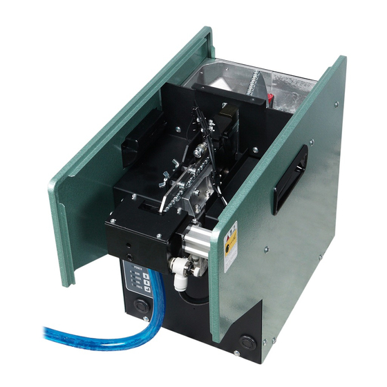
Vibratory Track Screw Feeder
FF/FM503H
Instruction Manual
Ver2
version
(For system
02.02、02.03)
FF503H type
Assembly Machine Division
NITTO SEIKO CO., LTD.
Table of
Contents
Previous
Page
Next
Page
1
2
3
4
5
Advertisement
Table of Contents
Need help?
Do you have a question about the FF503H and is the answer not in the manual?
Ask a question
Questions and answers
Related Manuals for Nitto Seiko FF503H
Industrial Equipment Nitto Seiko FM503H Instruction Manual
Vibratory track screw feeder (61 pages)
Industrial Equipment Nitto Seiko FF/FM311DR Instruction Manual
Compact drum type screw feeder (54 pages)
Industrial Equipment Nitto Seiko FF801H Instruction Manual
Vibratory track screw feeder (44 pages)
Industrial Equipment Nitto Seiko NITOMAN RC5500 User Manual
General-purpose robot controller (63 pages)
This manual is also suitable for:
Fm503h
Table of Contents
Save PDF
Print
Rename the bookmark
Delete bookmark?
Delete from my manuals?
Login
Sign In
OR
Sign in with Facebook
Sign in with Google
Upload manual
Upload from disk
Upload from URL


Need help?
Do you have a question about the FF503H and is the answer not in the manual?
Questions and answers