Chapters
Table of Contents

Related Manuals for General E Z Pro


Summary of Contents for General E Z Pro
- Page 1 No. 870 USER’S MANUAL (U.S. PATENTS APPLIED FOR) PLEASE READ THESE INSTRUCTIONS FULLY BEFORE USING THIS JIG For more information and video instructions visit www.generaltools.com/mortise-tenon...
-
Page 2: Table Of Contents
CONTENTS Introduction ..........3 Capacity and Specifications . -
Page 3: Introduction
INTRODUCTION Thank you for purchasing General Tools & Instruments’ E-Z ™ Pro Combination Mortise & Tenon Jig (M&T Jig)— the woodworking industry’s first integrated jig capable of making matching mortise and tenon joints of professional quality “right out of the box.” The jig makes creating Mortise &... -
Page 4: Anatomy Of The Jig
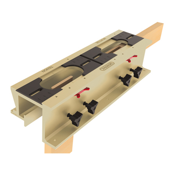
ANATOMY OF THE E-Z PRO MORTISE & TENON JIG Fig. 1 JIG ASSEMBLY IN PROFILE JIG ASSEMBLY TENON SECTION MORTISE SECTION 1 - Jig Assembly 4 - Centering Wall, [4A] Markings, [4B] Serrations, [4C] Thumb Screws 1A - Centering Marks 5 - Face Clamp Thumb Screws 1B - Centering Notches 6 - Positioning Bars... -
Page 5: Preparing The Router
Before using the router, check that none of its moving parts is broken, loose or misaligned. NOTE: General Tools & Instruments is not responsible for router misuse or the disregard of standard safety precautions associated with using a router. -
Page 6: Setting The Cutting Depth
Fig. 6 • Once you have completed this centering operation, remove the Centering Pin from the router and replace it with the router bit (Fig. 6). Setting the Cutting Depth • Set the depth of your plunge router for the desired depth of your mortise and tenon. •... -
Page 7: Operating Instructions
OPERATING INSTRUCTIONS: 1. Marking Joint Centers and Location Mark the stock with center marks at the positions for the length of the tenon and the mortise. These marks will be needed to center the tenon and the longitudinal position of the mortise on the stock. -
Page 8: Positioning The Stock Using The Positioning Bars
3. Positioning the Stock Using the Positioning Bars When in the deployed position (Fig 12), the Positioning Bars serve two basic purposes: 1. Then position the stock at the correct depth below the underside of the template for routing 2. Then align the stock so it is squared, at 90 degrees, to the jig longitudinally Fig. -
Page 9: Setting The Joint Length
4. Setting the Joint Length The M&T jig has two working sections, the mortise section and the tenon section (Fig. 16). Fig. 16 MORTISE SECTION TENON SECTION Both the mortise section and the tenon section of the jig are equipped with left and right Adjustable Sliding Templates [#2 &... -
Page 10: Setting The Depth Of The Router Bit
Both the tenon and mortise sections have has two Centering Marks [1A] (Fig. 17) which indicate the longitudinal center of the templates. There are also Centering Notches [1B] on the deployed Positioning Bars [6]; they indicate the center of the template’s width. TIP: It may be advisable to size the mortise slightly longer than the tenon (or the tenon slightly shorter than the mortise) for ease of insertion, adjustment and gluing. -
Page 11: Routing The Tenon
Fig. 21 6. Routing the Tenon 1/4" UP When routing the tenon, make sure the CUT BIT Guide Bushing [R-3] only rides against R-3 GUIDE SHOWN the outer edges of the tenon template [3] BUSHING (Fig. 21) at all times. 1. -
Page 12: Routing The Mortise
Fig. 24 7. Routing the Mortise Tip: when routing the mortise, it is advisable to increase the depth of cut slightly more than that of the tenon to allow space for glue to be put on the tenon before inserting it into the mortise. The Guide Bushing [R-3] fits the Mortise Template [2] (Fig. -
Page 13: Routing Other Size Mortise And Tenons
ROUTING OTHER SIZE MORTISE AND TENONS The E•Z Pro Mortise and Router Guide Bushing Tenon Jig Kit includes the guide sleeve with Locking Nut [R2, R1], a 1-1/8" Router Guide Bushing for 1/4" joints [R3], a 1/4" Upcut Spiral Router Bit and a Centering Pin [R4]. These parts will permit you to make 1/4" mortises and tenons suitable for 3/4"... -
Page 14: Customer Support
WARRANTY INFORMATION The No. 870 Mortise & Tenon Jig Kit from General Tools & Instruments is warranted to the original purchaser to be free from defects in material and workmanship for a period of one year. Subject to certain restrictions, General will repair or replace this product, if, after examination,... -
Page 15: Spanish Manual
PLANTILLA PARA MORTAJA Y ESPIGA No. 870 MANUAL DEL USUARIO (PATENTE PENDIENTE EN USA) LEA COMPLETAMENTE LAS INSTRUCCIONES ANTES DE UTILIZAR ESTA PLANTILLA PARA MÁS INFORMACION E INSTRUCCIONES DE VIDEO VISITE NUESTRA PÁGINA WEB www.generaltools.com/mortise-tenon... - Page 16 Preparando la Fresadora ........19 – 20 Información General de Seguridad ......19 Instalando el Manguito de Guía “Cambio Rápido”...
-
Page 17: Introducción
INTRODUCCIÓN Gracias por adquirir la E Z Pro Plantilla Combinación Mortaja y Espiga (M&T Jig) de General Tools & Instruments. La primer plantilla integrada en la industria de trabajos de madera con la capacidad de hacer combinaciones de ensambladura de Mortaja y Espiga de manera profesional “Lista para instalar”. -
Page 18: Anatomía De La Plantilla
ANATOMÍA DE LA E Z PRO PLANTILLA PARA MORTAJA Y ESPIGA Figura 1. ENSAMBLAJE DE LA PLANTILLA EN PERFIL ENSAMBLAJE DE LA PLANTILLA SECCIÓN DE LA ESPIGA SECCIÓN DE LA MORTAJA 1 - Ensamblaje de la Plantilla 4 - Pared de Centrado, [4A] Marcadores,... -
Page 19: Preparando La Fresadora
Verifique que ninguna pieza esté quebrada, floja o desalineada. NOTA: General Tools & Instruments no se hace responsable por el mal uso o por hacer caso omiso de las normas de precaución de seguridad asociadas con el uso de la fresadora. -
Page 20: Fijando La Profundidad Del Corte
Una vez completada la operación de centrado, remueva el perno de centrado de la fresadora Figura 6 y reemplace con la broca buriladora (Figura 6). Fijando la profundidad del Corte • Fije la profundidad de su fresadora de superficie para obtener la profundidad deseada de su mortaja y espiga. -
Page 21: Instrucciones De Operación
INSTRUCCIONES DE OPERACIÓN: 1. MARCANDO LA UBICACIÓN Y CENTROS DE LAS JUNTAS Marque la pieza con las marcas de centros en las posiciones para el largo de la espiga y la mortaja. Éstas marcas serán necesarias para centrar la espiga y la posición longitudinal de la mortaja de la pieza. -
Page 22: Fijando La Pieza Utilizando Las Barras Posicionadoras
3. POSICIONANDO LA PIEZA, UTILIZANDO LAS BARRAS POSICIONADORAS Cuando las barras posicionadoras están en la posición de despliegue (Figura 12), éstas sirven para 2 propósitos básicos: 1. Posicionar la pieza en la profundidad correcta debajo de la parte inferior de la plantilla para enrutamiento. -
Page 23: Fijando El Largo De La Junta
4. FIJANDO EL LARGO DE LA JUNTA La Plantilla de Mortaja y Espiga consta de 2 secciones de trabajo, la sección de la mortaja y la sección de la espiga (Figura 16) Figura 16 SECCIÓN DE LA MORTAJA SECCIÓN DE LA ESPIGA Tanto la sección de la mortaja como la sección de la espiga están equipadas con plantillas deslizantes ajustables, derecho e izquierdo [#2 y #3] (Figura 16) las cuales se utilizan para fijar el largo de la junta. -
Page 24: Fijando La Profundidad De La Broca Buriladora
Ambas Secciones, la mortaja y la espiga tienen dos marcas de centrado [1A] (Figura 17) las cuales indican el centro longitudinal de las plantillas. Cuenta también con ranuras de centrado [1B] en la las barras de posicionamiento desplegadas [6] ; éstas indican el centro del ancho de la plantilla. CONSEJO: Es recomendable darle a la mortaja un tamaño ligeramente más largo que la espiga (o la espiga un poco más corta que la mortaja) para fácil inserción, ajuste y pegado. -
Page 25: Enrutamiento De La Espiga
6. Enrutamiento de la Espiga Al momento del enrutamiento de la espiga, asegúrese que la manguita de guía [R3] se conduzca todo el tiempo Figura 21 únicamente en el sentido contrario de las orillas exteriores de la plantilla de la espiga [3] (Figura 21). -
Page 26: Enrutamiento De La Mortaja
Figura 24 7. Enrutamiento de la Mortaja Consejo: Al momento del enrutamiento de la mortaja, es recomendable aumentar ligeramente la profundidad del corte de la mortaja que el de la espiga, esto permite dejar espacio para la goma que aplicará en la espiga antes de insertarla dentro de la mortaja. La guía de cojinete [R3] encaja exactamente en la plantilla de la Mortaja [2] (Figura 24) lo cual evitará... -
Page 27: Enrutamiento De Otros Tamaños De Mortajas Y Espigas
ENRUTAMIENTO DE OTROS TAMAÑOS DE MORTAJAS Y ESPIGAS La E Z Pro Plantilla de Mortaja y Espiga y la guía de cojinete de la fresadora incluyen el manguito de guía con una tuerca de retención [R2, R1] y una guía de cojinete de 1-1/8" para juntas de 1/4"... -
Page 28: Soporte Al Cliente
INFORMACION DE GARANTÍA General Tools & Instruments garantiza al comprador original que el material y la fabricación del paquete de la Plantilla de Mortaja y Espiga No. 870 está libre de defectos durante un período de un año. Sujeto a ciertas restricciones, General Tools reparará o reemplazará este producto,... -
Page 29: French Manual
GABARIT À MORTAISE ET TENON N° 870 MANUEL DE L’UTILISATEUR BREVETS AMÉRICAINS DEMANDÉS VEUILLEZ LIRE ATTENTIVEMENT TOUT LE MANUEL AVANT D’UTILISER CE PRODUIT. Pour plus de détails et des instructions vidéo, visitez le site www.generaltools.com/mortise-tenon... - Page 30 TABLE DES MATIÈRES Introduction ..........31 Capacité...
-
Page 31: Introduction
INTRODUCTION Merci d’avoir acheté un gabarit à mortaise et tenon E-Z Pro de General Tools & Instruments – le premier gabarit intégré de l’industrie du travail du bois en mesure de faire des assemblages à mortaise et tenon de qualité professionnelle dès son déballage. Ce gabarit facilite et simplifie la fabrication de mortaises et tenons –... -
Page 32: Anatomie Du Gabarit
ANATOMIE DU GABARIT À MORTAISE ET TENON E-Z PRO Fig. 1 PROFIL DE L’ASSEMBLAGE DU GABARIT ASSEMBLAGE DU GABARIT SECTION TENON SECTION MORTAISE 1 - Assemblage du gabarit 4 - Barre de centrage, [4A] marques, [4B] dentelure, [4C] vis de serrage 1A - Marques de centrage 5 - Vis de serrage du serre-joints 1B - Embrèvements de centrage... -
Page 33: Préparation De La Toupie
à son utilisation. Avant d’utiliser la toupie, vérifiez qu’aucune de ses parties mobiles n’est brisée, lâche ou désalignée. REMARQUE : General Tools & Instruments n’est pas responsable du mauvais usage de la toupie ni de la non-observation des mesures de sécurité normales associées à l’utilisation d’une toupie. -
Page 34: Réglage De La Profondeur De La Coupe
Fig. 6 Une fois que l’étape du centrage est terminée, retirez la tige de centrage de la toupie et remplacez-la par la fraise de la toupie (fig. 6). RÉGLAGE DE LA PROFONDEUR DE LA COUPE • Réglez la profondeur de votre toupie plongeante à la profondeur désirée pour la mortaise et le tenon. -
Page 35: Instructions De Fonctionnement
INSTRUCTIONS D’UTILISATION : 1. Emplacement et marquage des centres de la mortaise et du tenon Faites des marques centrales aux positions correspondant à la longueur du tenon et de la mortaise. Ces marques seront nécessaires pour centrer le tenon et la position longitudinale de la mortaise sur le bois. -
Page 36: Positionnement Du Bois Avec Les Barres
3. Positionnement du bois avec les barres de positionnement Lorsqu’elles sont déployées (fig. 12), les barres de positionnement ont deux fonctions de base : 1. Positionner le bois à la profondeur adéquate sous le dessous du guide pour le passer à la toupie;... -
Page 37: Tableau Des Longueurs Des Mortaises Et Tenons
4. Réglage de la longueur des mortaises Le gabarit comporte deux sections de travail : la section mortaise et la section tenon (fig. 16). SECTION MORTAISE SECTION TENON Les sections mortaise et tenon du gabarit sont toutes deux dotées de guides coulissants ajustables [# 2 et # 3] (fig. -
Page 38: Réglage De La Profondeur De La Fraise
Les sections tenon et mortaise comportent toutes deux des marques de centrage [1A] (fig. 17) qui indiquent le centre longitudinal des guides. On trouve aussi des embrèvements de centrage [1B] sur les barres de positionnement [6]; ils indiquent le centre de la largeur du guide. TRUC : Il est conseillé... -
Page 39: Taille Du Tenon Avec La Toupie
6. Taille du tenon avec la toupie Lorsque vous taillez le tenon, veillez à ce que la douille de guidage [R-3] se déplace seulement contre les parois Fig. 21 extérieures du guide du tenon [3] (fig. 21) en tout temps. 1. -
Page 40: Taille De La Mortaise Avec La Toupie
Fig. 24 7. Taille de la mortaise avec la toupie Truc : Lorsque vous taillez la mortaise à la toupie, il est conseillé d’augmenter légèrement la profondeur de la taille par rapport à la longueur du tenon pour laisser de l’espace à la colle qui sera mise sur le tenon avant de l’insérer dans la mortaise. -
Page 41: Taille De Mortaises Et Tenons À La Toupie - Autres Formats
TAILLE DE MORTAISES ET TENONS À LA TOUPIE - AUTRES FORMATS L’ensemble de gabarit à mortaise et tenon E-Z Pro avec douille de guidage pour la toupie inclut un manchon de guidage avec contre-écrou [R2, R1], une douille de guidage pour la toupie de 1 1/8 po pour les assemblages de 1/4 po [R3], une fraise de 1/4 po et une tige de centrage [R4]. -
Page 42: Service À La Clientèle
INFORMATION SUR LA GARANTIE Le gabarit à mortaise et tenon n° 870 de General Tools & Instruments est garanti pour l’acheteur original contre tout défaut de matériau et de main-d’œuvre pour une période de un an. General réparera ou remplacera, sous certaines restrictions, cet instrument si, après examen, l’entreprise... - Page 43 NOTES ______________________________________________________________________ ______________________________________________________________________ ______________________________________________________________________ ______________________________________________________________________ ______________________________________________________________________ ______________________________________________________________________ ______________________________________________________________________ ______________________________________________________________________ ______________________________________________________________________ ______________________________________________________________________ ______________________________________________________________________ ______________________________________________________________________ ______________________________________________________________________ ______________________________________________________________________ ______________________________________________________________________ ______________________________________________________________________ ______________________________________________________________________ ______________________________________________________________________ ______________________________________________________________________ ______________________________________________________________________...
- Page 44 PHONE (212) 431 - 6100 FAX (212) 431 - 6499 TOLL FREE (800) 697-8665 e-mail: sales@generaltools.com www.generaltools.com 870 User’s Manual Specifications subject to change without notice ©2011 GENERAL TOOLS & INSTRUMENTS NOTICE - WE ARE NOT RESPONSIBLE FOR TYPOGRAPHICAL ERRORS. MAN#870 8/11 /11...
- Page 45 No. 870 ADDITIONAL TIPS & TRICKS TWO WAYS TO MORTISE A WORK PIECE THAT IS LESS THAN 2" WIDE Method #1 The center of the clamp which holds the work piece is 2" below the positioning bars so if you wish to clamp stock in the jig for mortising that is less than 2"...
- Page 46 Of course, as an alternative, the tenon may be sanded down to establish the desired fit as well. If, at any time, you need additional help, feel free to call a wood joining expert at General! GENERAL TOOLS & INSTRUMENTS...
Need help?
Do you have a question about the E Z Pro and is the answer not in the manual?
Questions and answers