Advertisement
Quick Links
DESCRIPTION
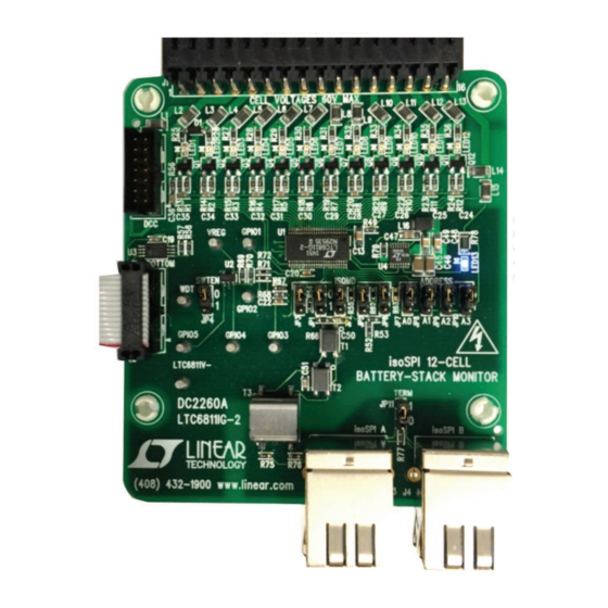
Demonstration circuit 2260A is an Addressable isoSPI
Battery-Stack Monitor featuring the LTC6811-2. Multiple
boards can be linked through a 2-wire isolated serial in-
terface to monitor any number of cells on a stack.
Communication to a PC uses a DC2026 Linduino
as a USB interface. The DC2026 comes preloaded with
a legacy DC590 emulator function (the DC590 can also
1
still be used
). A control program for up to ten stacked
boards has a Graphical User Interface (GUI) to implement
the device command set.
To control more than one DC2260A, the DC1941B isoSPI
adapter and RJ45 (Ethernet) patch cables are also required.
HARDWARE SETUP
When connected to a battery stack, power for the DC2260A
is provided by the cell group being monitored. Separate
the screw-terminal section from J1 and wire cell voltage
connections or resistors into the clamping contacts to
provide the input stimulus for the ADC.
Cell voltages are wired from position 4 (most negative
potential of the group) with increasing potentials up to
position 16 (most positive potential).
Design files for this circuit board are available at
http://www.linear.com/demo/DC2260A
L, LT, LTC, LTM, Linear Technology and the Linear logo and Linduino are registered
trademarks and QuikEval is a trademark of Linear Technology Corporation. All other
trademarks are the property of their respective owners.
1
A DC590 is a USB data acquisition board that serves to interface the DC2259 to a PC's USB
port. This board is not necessary with a DC2026.
DEMO MANUAL DC2260A
Addressable isoSPI Battery-
Alternatively, for a simple demo, connect twelve 100Ω
resistors between each contact from position 4 to position
16 as shown in Figure 1. Then, provide a "stack-equivalent"
power supply connection to position 16 (positive) and
position 4 (return). The supply may be adjusted to provide
One
®
the desired nominal cell voltage (e.g., 43.2V will be 3.6V/
cell). Note that cell discharge cannot be demonstrated
properly with a resistor string stimulus.
Photo 1 shows the following connections for one board
interfaced to a PC:
1. Set jumpers on the board per Figure 1.
2. Connect a USB cable from the PC USB port to DC2026.
3. Connect a 14-pin ribbon from DC2026 to the SPI con-
nector (J2) on DC2260A.
4. Mate the J1 cell-voltage connector. The blue LED will
illuminate when power is applied. The brightness reflects
the supply current.
Photo 1. Connecting a Board to a PC
LTC6811-2
Stack Monitor
dc2260af
1
Advertisement

Related Manuals for Linear Technology LTC6811-2


Summary of Contents for Linear Technology LTC6811-2
- Page 1 Design files for this circuit board are available at http://www.linear.com/demo/DC2260A L, LT, LTC, LTM, Linear Technology and the Linear logo and Linduino are registered trademarks and QuikEval is a trademark of Linear Technology Corporation. All other trademarks are the property of their respective owners.
- Page 2 DEMO MANUAL DC2260A DESCRIPTION Photo 2. Connections and Jumpers dc2260af...
- Page 3 DEMO MANUAL DC2260A DESCRIPTION Figure 1. Simple Cell Simulator Using Resistors dc2260af...
-
Page 4: Software Setup
TERMination jumpers (JP11) on DC2260A should all be set to “0” except for the unit electrically furthest from The LTC6811-2 can be operated using the isoSPI ports the DC1941 (JP11 set to “1”). (J3 and J4) rather than the conventional SPI port (J2), if desired. - Page 5 Figure 2 is the initial start-up screen that appears when configuration of the LTC6811-2 will be read from the the program is launched. Once power is supplied to the board. The Hex codes for the six bytes of configuration...
- Page 6 DEMO MANUAL DC2260A OPERATING THE CONTROL SCREEN Clicking the READ CONFIG button can give confirmation In the section labeled SET VOLTAGE LIMITS, click on the that the configuration change was actually made. Five of boxes and enter voltage values for the overvoltage and the six bytes read back should match the bytes sent and undervoltage thresholds appropriate for the cells being the PEC15/CRC15 check 16-bit words should be a match...
- Page 7 DEMO MANUAL DC2260A OPERATING THE CONTROL SCREEN measurements are displayed in groups of 3 when each The LTC6811 offers the option of keeping the discharge command button inside the READ CELLS box is clicked. transistors on while measuring the cell voltages. This is done using the STARTCELL DCC command button.
-
Page 8: Datalogging Operation
DEMO MANUAL DC2260A OPERATING THE CONTROL SCREEN For convenience, the control panel allows for continuous 1. At the upper left of the GUI, click on the Datalog Menu operation of the DC2260A board. When the command then Enable Datalog. button labeled START CONTINUOUS READ CELLS is se- lected, the GUI operates in a continuous loop executing the following command sequence automatically: Start cell voltage... -
Page 9: Software Adjustments
Information furnished by Linear Technology Corporation is believed to be accurate and reliable. However, no responsibility is assumed for its use. Linear Technology Corporation makes no representa- tion that the interconnection of its circuits as described herein will not infringe on existing patent rights. - Page 10 Linear Technology Corporation (LTC) provides the enclosed product(s) under the following AS IS conditions: This demonstration board (DEMO BOARD) kit being sold or provided by Linear Technology is intended for use for ENGINEERING DEVELOPMENT OR EVALUATION PURPOSES ONLY and is not provided by LTC for commercial use. As such, the DEMO BOARD herein may not be complete in terms of required design-, marketing-, and/or manufacturing-related protective considerations, including but not limited to product safety measures typically found in finished commercial goods.
- Page 11 Mouser Electronics Authorized Distributor Click to View Pricing, Inventory, Delivery & Lifecycle Information: Analog Devices Inc. DC2260A...
Need help?
Do you have a question about the LTC6811-2 and is the answer not in the manual?
Questions and answers