Table of Contents
Advertisement
Quick Links
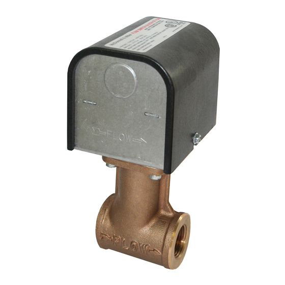
Series FS4-3T
General Purpose
Liquid Flow Switch
• Before using product, read and understand instructions.
• Save these instructions for future reference.
• All work must be performed by qualified personnel trained in the proper application,
installation, and maintenance of plumbing, steam and electrical equipment and/or systems in
accordance with all applicable codes and ordinances.
• To prevent electrical shock, turn off the electrical power before making electrical
connections.
• To prevent an electrical fire or equipment damage, electrical wiring insulation must have a
rating of 167˚F (75˚C) if the liquid's temperature exceeds 180˚F (82˚C).
• To prevent electrocution, when the electrical power is connected to the flow switch, do not
touch the terminals.
• Make sure flow switch electrical cover is secured before turning on electric power.
• Liquid m edia containing deb ris or other particulates should b e filtered to avoid dam age
to or ob struction of the flow switch paddle arm
Switch to m alfunction.
•
California Proposition 65 warning! This product contains chemicals known to the
state of California to cause cancer and birth defects or other reproductive harm.
•
Previous controls should never be installed on a new system. Always install new
controls on a new boiler or system.
Failure to follow this warning could cause property damage, personal injury or death.
CAUTION:
•
A more frequent replacement interval may be necessary based on the condition of
the unit at time of inspection. McDonnell & Miller's warranty is one (1) year from date
of installation or two (2) years from the date of manufacture.
INSTRUCTION MANUAL
assem b ly, which could cause the flow
MM-613E
Advertisement
Table of Contents

Related Manuals for Xylem McDonnell & Miller FS4-3T Series


Summary of Contents for Xylem McDonnell & Miller FS4-3T Series
- Page 1 INSTRUCTION MANUAL MM-613E Series FS4-3T General Purpose Liquid Flow Switch • Before using product, read and understand instructions. • Save these instructions for future reference. • All work must be performed by qualified personnel trained in the proper application, installation, and maintenance of plumbing, steam and electrical equipment and/or systems in accordance with all applicable codes and ordinances.
-
Page 2: Specifications
SPECIFICATIONS Maximum Liquid Pressure: 160 psi (11.3 kg/cm Liquid Temperature Range (T ): 32 - 300°F (0 - 149°C) Ambient Temperature Range (T ): 32 - 120°F (0 - 49°C) Electrical Enclosure Rating: NEMA Type 1 (IP 21) Maximum Velocity: 10ft/sec (3M/sec) Pipe Connection Thread Size: ”... -
Page 3: Flow Rates
FLOW RATES Settings will vary when used to sense flow of other Flow rates required to activate the flow switch are shown in chart below.These values were fluids. calculated using clean water in a horizontal pipe. Flow Rates Mode of Operation Max. -
Page 4: Installation
INSTALLATION – STEP 1 - Determine the Location of the Flow Switch • The flow switch should be located in a horizontal section of pipe where there is a straight horizontal run of at least 5 pipe diameters on each side of the flo w switch. -
Page 5: Step 3 - Electrical Installation
STEP 3 - Electrical Installation WARNING • To prevent electrical shock, turn off the electrical power before making electrical connections. • To prevent an electrical fire or equipment damage, electrical wiring insulation must have a rating of 167°F (75°C) if the liquid’s temperature exceeds 180°F (82°C). •... - Page 6 c. Determine which switch action is required for the flow switch. • “Flow” means that the switch will close circuit C.-N.O. and open circuit C.-N.C. when flow rate is increased above setpoint of flow switch. • “No Flow” means that the switch will open circuit C.-N.O.
-
Page 7: Section 5 - Adjustment
STEP 4 - Testing a. Place cover on flow switch and turn on power. Initiate fluid flow through the system. Observe the device being activated by the flow switch to determine if device is operating as required. b. Turn off fluid flow to determine if device is operating as required. - Page 8 Xylem Inc. 8200 N. Austin Avenue Morton Grove, Illinois 60053 Phone: (847) 966-3700 Fax: (847) 965-8379 www.xyleminc.com/brands/mcdonnellmiller McDonnell & Miller is a trademark of Xylem Inc. or one of its subsidiaries. E July...