Table of Contents
Advertisement
Quick Links
Advertisement
Table of Contents

Related Manuals for ICS Tunnel Master wbc

Summary of Contents for ICS Tunnel Master wbc
- Page 1 Tunnel Master® wbc Installation Guide Version 11.0...
- Page 2 Information in this manual is subject to change without notice. The example companies, organizations, products, domain names, email addresses logos, people, places and events depicted herein are fictitious. No association with any real company, organization, product, domain name, email address, logo, person, place, or event is intended or should be inferred unless otherwise noted.
-
Page 3: Table Of Contents
Contents Installation Overview ............................2 Hardware Specs ............................. 2 Site Planning ................................3 Determine the Location ..........................3 Planning for Installation ..........................3 Mounting Template for the Tunnel Master® wbc ................4 Equipment Dimensions ..........................5 Conduit Run Guidelines ..........................5 Site Grounding Considerations ........................ - Page 4 Adding a Second Relay ..........................27 Jumper Test Point Locations ........................29 Terminal Block ..............................30 Input Name ..............................30 Description ..............................30 DIP Switch and Reset Button ........................32 DIP Switch Settings ............................33 Third Party Kiosk to Tunnel Master® wbc Terminations ..............34 Third Party Kiosk to WBC Terminations ....................35 Ultrasonic Truck Bed Sensor ........................36 Ultrasonic Truck Bed Sensor Mounting Recommendations ............37 Exterior of Tunnel Master®...
- Page 5 Figure 25. DIP Switch and Reset Button ....................32 Figure 26. DIP Switch (Input Board) ......................33 Figure 27. Non-ICS Kiosk (not an Auto Sentry) to Tunnel Master® wbc Terminations ..35 Figure 28. Exterior Panel ...........................36 Figure 29. Ultrasonic Truck Bed Sensor Mounted................36 Figure 30.
- Page 6 Figure 35. Ultrasonic Sensor Comm Connections ................42 Figure 36. Power for the Sensor (Black, brown, and blue wires) ..........43 Figure 37. Ultrasonic Sensor detecting a pickup truck ..............44 Figure 38. RS-232 Comm Terminal Wiring Diagram (Main CPU Board) ........46 Figure 39. RS-485 Communication Wiring Layout ................48 Figure 40.
- Page 7 List of Tables Table 1. Tools Required and Parts Included ..................1 Table 2. Equipment Dimensions ......................5 Table 3. Wire Gauge and Conduit Size ....................6 Table 4. Internal Components of Tunnel Master® wbc ..............8 Table 5. Main CPU Board Inputs ......................10 Table 6.
-
Page 8: Table 1. Tools Required And Parts Included
1 – 5A fuse (FUSE5) 5 – ¼” x 20 nuts, flat washers, lock washers 8 – #10 x 32 nuts 2 – ICS screwdrivers 1 – set of 2 keys for the Tunnel Master® wbc door 20 – jumpers (WBCJUMP214) 1 –... -
Page 9: Installation Overview
Many of the WBC system features were integrated at the request of current car wash operators. We welcome your feedback and want to assure you that ICS will always remain the industry leader in car wash controller and management systems. -
Page 10: Site Planning
Power for the Tunnel Master® wbc and any peripherals must come from the dedicated UPS, as „ supplied by ICS. „ The Tunnel Master® wbc and peripheral equipment must be properly grounded. Tunnel Master® wbc Installation Guide... -
Page 11: Mounting Template For The Tunnel Master® Wbc
Mounting Template (For reference Only, this is not the actual template.) Mounting Template for the Tunnel Master® wbc 2" 24" Center to Center 9/16" Dia. 5/8" Detail Notch 9/16" Diameter 36" Center to Center 4" 4" ½” Bolts Recommended 9/16" Diameter Detail 9/16" Dia. 2" Figure 1. Tunnel Master® wbc Mounting Template Tunnel Master® wbc Installation Guide Tunnel Master®... -
Page 12: Equipment Dimensions
Equipment Dimensions When mounting the Tunnel Master® wbc unit, minimum clearances must meet local codes. Dimension Amount Notes Width 32'' — Height 40'' — Depth 12'' Includes the plastic face. Weight 130 lbs Inclusive of the box, board, and door. 32°... -
Page 13: Site Grounding Considerations
Wire Gauge and Conduit Size When planning the orientation of the wiring runs, follow the applicable ICS wiring diagrams and consider the layout of the components at the site. To determine conduit size needed, see the table below for more information. -
Page 14: Electrical Installation
Electrical Installation The Tunnel Master® wbc is the control center for “firing” the various outputs or services in the wash tunnel: soap foamer, reclaim motor, and more. The Tunnel Master® wbc provides for automatic, computer controlled, or manual firing of the outputs. The system can control up to 192 outputs and 64 inputs (48 of which are user-programmable). -
Page 15: Figure 2. Internal Components
Tunnel Master® wbc Internal Components Figure 2. Internal Components Description Relay Board 1 Relays 1-24 Relay Board 2 Relays 25-48 Relay Board 3 Relays 49-72 Relay Board 4 Relays 73-96 Input Board Main CPU Board 24V DC Power Supply 12V AC for all Isolated Inputs Table 4. - Page 16 Tunnel Master® wbc Main CPU Board Figure 3. Main CPU Board Tunnel Master® wbc Installation Guide Page 9...
-
Page 17: Main Cpu Board
Main CPU Board The following table lists inputs available on the main CPU board. All inputs require 24 V max. line, neutral, and ground. WARNING: *Removing the Flash Module for any reason will Void the Warranty. Description Description RJ-45 Terminal for Network Connection Display Connection Point Flash Module* Keyboard Connect Point... -
Page 18: Input Board Terminal Blocks
LEDs are available for all the I/Os including the RS-232/485 connections. „ LED indicators display the status of inputs. The main status LEDs include the following: „ • LED1–Logic • LED2–Auto pulse • LED3–6 Reserved • LED7–Chain travel • LED8–Conveyor Status Input Board Terminal Blocks Figure 4. -
Page 19: Delayed Panic Input
Terminal Block Input Name Description General note: ICS highly recommends Assigned Function Inputs GATE (SIGNAL) Using shielded cable for all input wiring. TIRE (SWITCH) Terminate the shield drain as close to the ROLLER LOCATOR 24 V AC power supply as possible. -
Page 20: Figure 6. Input Board Components
The input board provides monitoring and error reporting of all 48 inputs wired to the inputs terminal block. Auxiliary inputs help report the state of the tunnel. If an error condition or event occurs, you can use the inputs as monitors to receive alerts or set the tunnel into a panic stop mode. The input board works independently of the main CPU board. -
Page 21: Manual Bypass Operation
Input Board RJ-45 Terminal Additional Output Terminal DIP Switch 1 Fuse 6.3A Remote 24V DC Power Conveyor Output Terminal (If Remote Mount) 24V DC Power from ICS Provided Fuse 6.3A Power Supply Fuse 6.3A Horn Output Terminal Fuse 500mA Fuse 6.3A Fuse 6.3A... -
Page 22: Transformer Selection
TERMINAL connector will be used for dry contact operation -- Not Recommended. Transformer Selection Figure 8. Transformer Selector on the Input Board Auxiliary Input Internal Voltage Wiring- Dry Contact ICS does not recommend internal voltage for Auxiliary Inputs. ICS recommends external voltage. Auxiliary Input Relay Terminal Strip COMMON NORMALLY... -
Page 23: Figure 10. Auxiliary Input External Power Wiring
Auxiliary Input External Power Wiring ICS does not recommend internal voltage for Auxiliary Inputs. ICS recommends external voltage. 24 Vdc or 24Vac Auxiliary Input Relay Terminal Strip External Power Supply COMMON NORMALLY OPEN Examples: Low Air Pressure Low Hydraulic High Water or other Sensing Device Alternate symbol for N.O. -
Page 24: Relay Boards Components
Relay Boards Components The Tunnel Master® wbc ships with one relay board (standard). Up to three additional boards can be mounted inside the box. The extra relay boards are optional and additional fees apply. Separate data and power cables are used for each board. Each board supports 24 relays for a total of 96 [24 ×... -
Page 25: Jumpers
Then, the commons can be tied together via the supplied six-pole jumpers or daisy- chained individually with the appropriate gauge wire. This power is to “fire” the solenoids and equipment. Jumpers ICS supplied six-pole jumpers for relay board „ terminal block wiring. Phoenix Contact®, order number 1733 208, Part EBP 6-5 Figure 12. -
Page 26: Manual Bypass, Conveyor, And Horn Wiring
NOTES: 1. Each momentary start/stop station must be home-run with 18/4 shielded cable back to the input- conveyor interlock board inside the controller cabinet. The station may be with or without a lockout on the stop circuit. If a mechanical interlock exists between the start and stop circuits within this station, it must be removed prior to testing the conveyor. -
Page 27: Conveyor Relay Wiring
NOTES: 1. The manual bypass relay will activate and deactivate as the conveyor relay does. Any piece of tunnel equipment that is meant to be on and off with the conveyor, should be terminated to this relay. 2. The conveyor relay will activate upon the start circuit being momentarily closed or a wash having been loaded into the controller, dependent upon how the controller is programmed. -
Page 28: Conveyor Relay Wiring On Input And Relay Boards
Conveyor Relay Wiring on Input and Relay Boards Figure 15. Wiring of On-Board Relays for Conveyor Start Circuit Tunnel Master® wbc Installation Guide Page 21... -
Page 29: Pulse Switch Wiring
BELOW ARE EXAMPLES OF PROXIMITY SWITCH WIRING. PLEASE CONFIRM THE TYPE OF WIRING REQUIRED PRIOR TO ANY WIRE SINKING JUMPER CONFIGURATION TERMINATION SOURCING JUMPER CONFIGURATION ICS HIGHLY RECOMMENDS USING 18 / 2 SHIELDED CABLE SINK 2-WIRE PULSE SWITCH SOURCE ICS HIGHLY RECOMMENDS... -
Page 30: Main Inputs Wiring
Jumpers for each input must be set to external voltage 24 V AC. NOTE 1: Optimally, the roller locator switch should be wired normally closed to the ICS controller. Wiring the roller locator switch normally open is acceptable but will mean waiting longer for the roller to fire. -
Page 31: Common Relay Output Wiring
Common Relay Output Wiring Common relay output wiring is to be done on the relay board. COMMON RELAY OUTPUT WIRING SITE SUPPLIED 24VAC TRANSFORMER 24VAC SUPPLY FOUR PRONG TERMINAL JUMPER 24VAC SOLENOID TWO PRONG TERMINAL JUMPER Figure 18. Common Relay Output Wiring On the Relay Board, each relay is referred to as a channel (channels 1 through 24 on each relay board). - Page 32 If sequential relays will be controlling devices that require the same voltage, jump the required voltage through the commons using the prefabricated shorting bars provided by ICS. Each terminal jumper is long enough to connect the commons for six consecutive channels. If a lesser number of channel commons are to be connected, simply cut off those not needed with pliers.
-
Page 33: Common Relay Output Channels
Common Relay Output Channels Figure 19. Common Relay Output Channels Tunnel Master® wbc Installation Guide Tunnel Master® wbc Installation Guide Page 26 Page 26... -
Page 34: De-Selecting A Selective Relay Wiring
De-Selecting a Selective Relay Wiring The reason for turning off a selective function on a wash is if a customer requests this. A customer requesting to disable the tire shine for their wash is an example. Typically, the tire shine is a selective option. -
Page 35: Figure 22. Horizontal View Of Two Relay Setup
Figure 22. Horizontal View of Two Relay Setup WBC Relay Board Terminal Blocks N.O. N.C. Power In Example Diagram of Relay Connections for Retracts Power Out N.O. N.C. WBC RELAY BOARD Example Diagram explanation : Using R1, as Normally Open, in this example as the main contact that powers the output when "ON"... -
Page 36: Jumper Test Point Locations
Jumper Test Point Locations Figure 24. Jumper Test Point Locations This section explains the location and purpose of the jumpers on the Tunnel Master® wbc circuit boards. Tunnel Master® wbc Installation Guide Page 29... -
Page 37: Terminal Block
The following table describes jumper functions and settings: Jumper Jumped Not Jumped Transformer Selection. Both jumpers must be in either the E or I position, depending on the application. This is for the voltage required for the user-configurable inputs. Position I will use the voltage from JP25 to supply power to the individual inputs. (Dry Contact). (Default). Position E will need to have voltage supplied between the COM and the individual inputs. -
Page 38: Table 9. Jumper Functions And Settings
Jumper Jumped Not Jumped TP31 INPUT4 input selection. TP32 INPUT5 input selection. TP33 INPUT6 input selection. TP34 INPUT7 input selection. TP35 INPUT8 input selection. TP36 INPUT9 input selection. TP37 TP38 GATE input selection. TP39 TIRE input selection. TP40 ROLLER LOCATOR input selection. TP41 REMOTE ROLLER input selection. -
Page 39: Description
DIP Switch and Reset Button DIP Switch and reset buttons are located on the Main CPU Board. Dip switch default settings are OFF. After setting DIP Switch to ON, press Reset button on Main CPU board to activate. DIP Switch Reset Button Figure 25. -
Page 40: Dip Switch Settings
DIP Switch Settings DIP Switch Figure 26. DIP Switch (Input Board) Switch Settings: 0 = off (opened) 1 = on (closed) DIP Switch Function Setting Defaults SW1 & SW2 Horn-on time Sec. (On) SW3 & SW4 Delay after horn, before Sec. -
Page 41: Third Party Kiosk To Tunnel Master® Wbc Terminations
Terminations for the 3 AWG wires should be torqued to 20 pound-inches (2.3 n-m.) Over torquing may cause enclosure breakage. Electrician must run a single-twisted pair, 24AWG shielded com cable (can be purchased from ICS) through 3/4” conduit from the relay box to the Entrance Keypad. -
Page 42: Third Party Kiosk To Wbc Terminations
STACKING = ON INPUT DEVICE = PUSH BUTTON (IF NO KEYPAD) INPUT DEVICE = PUSH BUTTON AND KEYPAD (IF KEYPAD) Figure 27. Non-ICS Kiosk (not an Auto Sentry) to Tunnel Master® wbc Terminations Tunnel Master® wbc Installation Guide Page 35... -
Page 43: Ultrasonic Truck Bed Sensor
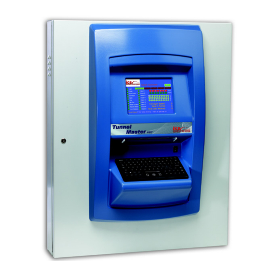
Exterior of Tunnel Master® wbc Description The display is a 640 × 480 color monitor. On-board Keyboard. Table 12. Exterior Descriptions of the Tunnel Master® wbc Figure 28. Exterior Panel Ultrasonic Truck Bed Sensor The ultrasonic sensor can detect the bed of a pickup truck. NOTE: This feature is optional and additional fees apply. -
Page 44: Ultrasonic Truck Bed Sensor Mounting Recommendations
If any of the Ultrasonic Mounting Recommendations cannot be met, a custom mounting † solution can be fabricated for your location. Contact your ICS sales representative for more information. Additional charges may apply. Mounting height must be at 9 feet. -
Page 45: Ultrasonic Truck Bed Sensor Power Supply Wiring
Ultrasonic Truck Bed Sensor Power Supply Wiring Wire the Ultrasonic Sensor to the power supply within Tunnel Master® wbc. Terminal blocks are located in the bottom right of the Tunnel Master® wbc. There is only 35’ of cable that runs from the sensor to the converter box. -
Page 46: Truck Bed Sensor Power Terminations
Ultrasonic Converter box. Ultrasonic Sensor Wiring Sensor communication connections are RS-485. ICS recommends wiring the ultrasonic sensor on a dedicated line. Avoid wiring additional devices: a keypad or smart relay box on the same line as the ultrasonic sensor. Two RS-485 communications ports are available on the Tunnel Master® wbc. Use one port for the ultrasonic sensor, and the other for additional devices. -
Page 47: Ultrasonic Sensor Jumper Settings
ICS Supplied 24/4 Comm Cable Figure 35. Ultrasonic Sensor Comm Connections ICS recommends leaving RS-485 jumpers unterminated on the Tunnel Master® wbc main CPU board. If the ultrasonic sensor is tested and returns communication errors, then you can terminate one or both RS-485 jumpers. -
Page 48: Powering The Ultrasonic Sensor
Powering the Ultrasonic Sensor Locate the gray power cable coming from the Ultrasonic Sensor. Connect three of the five wires from the gray power cable as follows: 1. The brown wire connects to the orange terminal block (+24 V DC). 2. -
Page 49: Figure 37. Ultrasonic Sensor Detecting A Pickup Truck
The ultrasonic sensor operation for detecting a bed for a pickup truck is shown in Figure 37. Figure 37. Ultrasonic Sensor detecting a pickup truck Sensor Settings for letters A and B shown in the figure above are described in the table below. Letter Field Name Recommended Setting*... -
Page 50: Communications Wiring
Communications equipment signal wires must also be run in separate rigid PVC or metal „ conduit, separate from any power conduit. 24/4 Comm Cable (can be purchased from ICS). „ RS-232 COMM Terminal Wiring Diagram Wiring to be done on the main CPU board. -
Page 51: Rs-485 Communication Wiring Layout
In Figure 38, you can see the sample layout for a Tunnel Master® wbc system with the double Tunnel Master Jr. configuration with 144 outputs. RS-485 Communication Cable Layout for a Tunnel Master wbc System with a Double Junior Configuration 96 + 24 + 24 =144 Outputs Tunnel Master Jr. -
Page 52: Install Entrance Keypad
— Max Amps .02 Amps. — Power must come from a Power Supply .02 Amps. dedicated ICS transformer. The keypad is rated for total protection against dust and IPX Rating IP65 strong jets of water from all directions, imitied ingress permitted. -
Page 53: Figure 40. Keypad Connectors (Keypad Board)
The following picture shows the connection points for the various components of the keypad and the table below provides descriptions of the numbered items in the image. Figure 40. Keypad Connectors (Keypad Board) Description Optional Pole Display screen termination point. Communications wire termination points. -
Page 54: Entrance Keypad Terminal Blocks
Entrance Keypad Terminal Blocks There is a terminal block (POWER) located on the keypad circuit board labeled with ACH „ (Line), ACN (Neutral), and then to the Ground Lug (Ground). Terminations for the 4 – 18 AWG wires should be torqued to 5.31 in. lbs to 7 in. lbs (.6 - .8 Nm). NOTE: Over torquing may cause enclosure breakage. -
Page 55: Tunnel Master® Wbc Ac Power Terminations
Tunnel Master® wbc AC Power Terminations Tunnel Master® wbc AC Power Terminations EMI FILTER 120 VAC NEUTRAL This side is the ICS side of the TERMINALS 120 VAC LINE FUSED WARNING: DO NOT USE terminal blocks for the TERMINAL FOR ICS USE ONLY Tunnel Master®... -
Page 56: Entrance Keypad Comm Cable
Electrician must run a single-twisted pair, 24 AWG shielded comm cable (can be purchased „ from ICS) through 3/4” conduit from the Tunnel Master® wbc 485 terminal to the entrance keypad. There is a terminal block (NETWORK 485), located on the keypad circuit board labeled with „... -
Page 57: Entrance Keypad Components
In Figure 43, the jumper functions are displayed with their normal settings. By default, the keypad is address 5. There is no reason to change this unless advised by ICS. If you have two keypads, you should address the second keypad as address 6. -
Page 58: Entrance Keypad Dip Switch Settings
Entrance Keypad DIP Switch Settings The following picture and table shows the Entrance Keypad DIP switch and the various settings that may be used. NOTE: The OFF position is toward the word OPEN or CONFIG on the circuit board. The following picture shows the DIP Switch on the Keypad cover. Figure 45. -
Page 59: Second Entrance Keypad Wiring
Table 21. Network 485 Second Entrance Comm Cable Electrician must run a single-twisted pair, 24 AWG shielded COM cable (can be purchased from ICS) through the above 3/4” conduit from the first entrance keypad to the second entrance keypad. Tunnel Master® wbc Installation Guide Tunnel Master®... -
Page 60: Troubleshooting
The application file is located on the site server. It can be started with a desktop shortcut. The executable is in \\ICS\CLS\. A network connection to the Tunnel Master® wbc is required. Plug the network cable into the RJ-45 terminal on the WBC main CPU board. - Page 61 Index Install Entrance Keypad 46 Site Planning 6 Auxiliary Input External Power Internal Components 11 Start/Stop Inputs Wiring 21 Wiring 19 Auxiliary Input Internal Voltage Jumpers 21 Third Party Kiosk 35 Wiring- Dry Contact 18 Jumper Test Point Locations 30 Transformer Selection 18 Troubleshooting 53 Central Log Server 53...
- Page 62 If you have any questions or concerns, please contact ICS Technical Support: 800-246-3469. Corporate Office: 81 Highland Avenue, Suite 300, Bethlehem, PA 18017 | Sales: 800.642.9396 Email: sales@icscarwashsystems.com | icscarwashsystems.com...
Need help?
Do you have a question about the Tunnel Master wbc and is the answer not in the manual?
Questions and answers