
Subscribe to Our Youtube Channel
Related Manuals for ICS Auto Sentry Petro

Summary of Contents for ICS Auto Sentry Petro
- Page 1 Auto Sentry® Petro Installation Guide - Version 4.1 Defining the World of Car Wash Technology...
- Page 2 Innovative Control Systems, Inc. (ICS) ICS and its product trademarks in this manual are trademarks of Innovative Control Systems. All other marks are property of their respective owners.
-
Page 3: Table Of Contents
Auto Sentry Petro Door Swing Clearance........ - Page 4 Interior rear left-side of Auto Sentry® Petro ........37 Interior Rear Door Components .
-
Page 5: Chapter 1: Site Layout
CHAPTER 1: Site Layout Careful planning for the layout of the site will help eliminate possible problems with the startup of your system. This document is intended to provide instructions to properly install the Auto Sentry® Petro to ensure continued, reliable system operation. All site wiring must be performed by a licensed electrician that must comply with all local and ... -
Page 6: Conduit Wiring Guidelines
Conduit Wiring Guidelines All conduit must be rigid PVC or metal. High-voltage (AC) and low-voltage (DC) must not be combined in a common conduit, junction box, or wire trough. Equipment Dimensions, Measurements, and Ratings When mounting the unit, minimum clearances must meet local recommended standards. Dimension Amount Notes... -
Page 7: Grounding
Grounding The Auto Sentry® Petro and peripheral equipment must be properly grounded. Recommended and Accepted Grounding Methods Proper system grounding is an extremely important part of the system installation. Grounds for all system devices should be wired to the breaker panel ground bus bar which, in turn, should be grounded to a ground rod. -
Page 8: Wire Gauge And Conduit Size
Wire Gauge and Conduit Size When planning the orientation of the wiring runs, follow the applicable ICS wiring diagrams and consider the layout of the components at the site. To determine conduit size needed, see the Table 2: ½ ¾... -
Page 9: Auto Sentry® Petro In-Bay Layout
IN-BAY LAYOUT *** THIS DRAWING IS ONLY INTENDED TO SHOW THE GENERAL LAYOUT AND DIMENSIONS NECESSARY FOR THE PROPER PLACEMENT OF THE AUTO SENTRY PETRO. ANY DEVIATION NOTE: ICS DOES NOT RECOMMEND AN IDEAL DISTANCE BETWEEN THE MAY CAUSE DAMAGE TO THE AUTO SENTRY PETRO. ***... -
Page 10: Auto Sentry® Petro Placement Front And Side View
Auto Sentry® Petro Placement Front and Side View Front The face of the Auto Sentry Petro is to be in line with the front edge of the curbing. Back The rear wall of the Auto Sentry Petro should be set at 14" from the front edge of the curbing. -
Page 11: Auto Sentry® Petro Dimensions
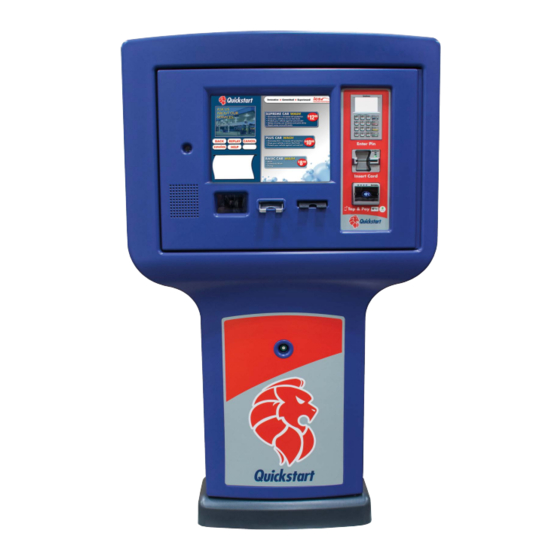
Auto Sentry® Petro Dimensions 15 ½” 31 ½” 16" 8" Side View Front View The Auto Sentry® Petro is the primary point of sale for the car wash. It is installed outside near the entrance of the car wash with a canopy placed over it. NOTE: Any curbing and raiser must be added to these measurements. -
Page 12: Auto Sentry® Petro Placement Top View
Auto Sentry® Petro Placement Top View AUTO SENTRY PETRO BASE PLACEMENT TOP VIEW BACK EDGE OF CURB CONCRETE ISLAND OPEN SPACE IN BASE OF AUTO SENTRY FOR PLACEMENT OF CONDUITS 6.06" x 6.06" 16" 14" 8" DIRECTION OF FRONT EDGE... -
Page 13: Auto Sentry Petro Door Swing Clearance
REAR EDGE OF ISLAND CURBING IMPORTANT: Leave an additional area behind the door clearance area for a technician to stand and work inside the Auto Sentry Petro. Figure 5. Auto Sentry Petro Door Clearance Auto Sentry® Petro - Installation Guide Site Layout... - Page 14 End of Chapter This-page is blank intentionally. Auto Sentry® Petro - Installation Guide Site Layout...
-
Page 15: Chapter 2: Molded Plastic Installation
Attaching the Auto Sentry® Petro to the J Bolts If your site does not have a raised curb, contact ICS to order a riser to place your Auto Sentry® Petro upon. The riser gives the Auto Sentry® Petro the proper height that is necessary to deliver to your customers who are inside their vehicles the most ergonomic, easy to reach experience at the Auto Sentry®... -
Page 16: Roto Molded Plastic Installation
Roto Molded Plastic Installation After the Auto Sentry® Petro is secured to the concrete with the J bolts, the next step is to attach the five Roto Molded Plastic pieces to the metal core of the Auto Sentry® Petro using the hardware in the following labeled plastic bags: Bag A (6) 1/4”... - Page 17 If there is no sidewalk, a 6” metal riser is required to raise the Auto Sentry® Petro to optimal ergonomic height. (Figure 15 demonstrates the 6” riser.) 1. Lift up the base of the Auto Sentry Petro and place over the U-bolts. Figure 8. (6) holes in metal base line up with plastic There are two small Roto Molded gray plastic pieces #1 and #2 that fit together to cover the base of the metal pedestal.
- Page 18 6. Locate the gray full-size Auto Sentry® Petro roto mold #3. See Figure 10. Figure 10. Roto Mold Plastic #3 (Front view) 7. On the Auto Sentry® Petro, open the front door to perform the next step. 8. Remove the plastic keeper on the sonic sensor. You will need to put this back on after the plastics are completely installed.
- Page 19 10. Use a #2 Phillips screwdriver and install (4) 1/4” × 20 × 1- 1/2” oval screws (Bag B). There are 10 holes but you only need to use four of the 10, preferably below the sonic sensor. See Figure 11. Figure 11.
- Page 20 15. At the top of the blue and gray molds, you can line up the screw holes. See Figure 14. NOTE: The (4) silver screw holes across the top of Roto Mold #4 are for optional sign attachment. Contact ICS Marketing for custom toppers for an additional fee. Auto Sentry® Petro - Installation Guide Molded Plastic Installation...
- Page 21 16. Install and tighten (3) #10 x 1- 1/2” screws with #8 flat washers (Bag C) across the top of the blue roto mold front cover. See Figure 14. Figure 14. Attach Blue Roto Mold #4 with 3 screws to gray Roto Mold #3 17.
- Page 22 18. Attach the metal mounting plate with the ribs facing out to the back of the Auto Sentry® Petro pedestal with (8) 1/4” x 20 × 3/8” bolts (Bag E). See Figure 16. Ribs facing Figure 16. Attach Metal Mounting Plate with 8 Bolts Auto Sentry®...
- Page 23 19. Install and tighten (14) #8 x 11 x 1- 1/4” screws and flat washers (Bag D & I) around the perimeter of the metal mounting plate. See Figure 17. Figure 17. Attach 14 Screws in the perimeter of the metal plate 20.
- Page 24 Figure 18. Roto Mold #5 for the Auto Sentry® Petro (Back Piece) DO NOT OVER TIGHTEN for steps #20 and #21. Five pound-foot torque is recommended. Over torquing could cause shearing or cracking. 21. Install and tighten (4) #8-11 X 1-1/4” (Bag D & I) across the top of the backside of Roto Mold #5. See Figure 18.
-
Page 25: Chapter 3: System Wiring
The warning symbol is below: WARNING: The terminals and power supplies contained in the Auto Sentry® Petro enclosure are for the ICS Equipment Only! Connecting external components and wiring to the Auto Sentry® Petro power circuits can damage the circuit boards and components and WILL VOID THE WARRANTY. -
Page 26: Auto Sentry® Petro Ac Power Terminations
NOTE: THIS PROGRAMMING GUIDE IS FOR THE ROUND WHITE/GREEN SONIC SENSOR NOT THE ORANGE SENSOR. 1) Put something in front of the sensor the same distance away from the Auto Sentry Petro where a car would normally be when parked at the payment terminal. (A metal sign works best or something similar). -
Page 27: Power Wiring Layout
*** THIS DRAWING IS ONLY INTENDED TO SHOW THE TYPES OF Main Service Electrical Panel providing an individual Line, WIRING THAT MUST BE RUN BETWEEN PIECES OF ICS Neutral, and Ground to each Auto Sentry for the Heat EQUIPMENT. THE INDIVIDUAL RUNNING THE WIRING MUST Exchanger. -
Page 28: Control Box Terminations
Control Box Terminations This feature is optional. WashConnect software has the ability to toggle the Auto Sentry® Petro Wash Open on the server /POS computer screen. Override switches for the gates are still necessary. ALL ITEMS CIRCLED TO BE PROVIDED BY CAR WASH SPST SWITCH PETRO (GRAINGER Part# - 2X464) -
Page 29: In-Bay Controller Wire Terminations
In-Bay Controller Wire Terminations TERMINATION POINTS ON AN IN-BAY AUTOMATIC CONTROLLER WASH ENABLE WASH ENABLE WASH IN USE WASH IN USE SERVICE #1 SERVICE #2 SERVICE #3 SERVICE #4 SERVICE #5 SERVICE #6 SERVICE #7 SERVICE #8 SERVICE #9 IN-BAY SUPPLIED VOLTAGE Terminology varies. -
Page 30: In-Bay Wiring Layouts
Figure 24 is an example of a possible Network Communication Layout for an In-Bay Car Wash. See the ICS System Installation Drawings that were prepared for your specific car wash site and given to you by your ICS salesperson or technician. -
Page 31: Chapter 4: Communications Wiring
Ethernet Networking PLUGGED INTO NETWORK PLUGGED INTO SWITCH PORT INSIDE NETWORK ROUTER AUTO SENTRY PETRO Pin Signals - Ethernet 1 2 3 4 5 6 7 8 1 2 3 4 5 6 7 8 1 - Transmit + 2 - Transmit -... -
Page 32: System Network Cables
Network Connection Figure 26. Network Connection inside the stand-alone Auto Sentry Petro 1 From the network router, pull a network cable up through the center of the Auto Sentry® Petro unit and plug it into the port on the network bracket located inside the stand-alone Auto Sentry. -
Page 33: Chapter 5: Parts Identification
If you have a 6” sidewalk above finished grade, you do not need the 6” riser. If there is no sidewalk that rises above the finished grade to install the Auto Sentry Petro upon, the 6” riser is necessary to provide optimal touch screen ergonomics. - Page 34 CAMERA Camera AS2INTERCOMSP 2 Speakers SCN-000002-00 Bar code Reader AS4CARDCHUTE Gift card dispenser chute for the Auto Sentry Petro SENSOR-18MML Replacement Sensor only PIN pad per site specifics Card reader assembly per site specifics Contactless reader per site specifics ASPRHEC USB printer Auto Sentry®...
-
Page 35: Power Terminal Blocks
Power Terminal Blocks Figure 28. Power Terminal Blocks ICS Part Description Number Power terminal blocks inside the Auto Sentry Petro AS4PWRSWITCH Power switch, illuminated Auto Sentry® Petro - Installation Guide Parts Identification... -
Page 36: Interior Front Door Components
USB Receipt Printer AS4CARDCHUTE Gift Card Chute AS3CARDDISP Card Dispenser Contactless reader per site specifics DISP15ON2 Display CAMERA Camera AS2INTERCOMSP 2 Speakers for the Auto Sentry Petro SCANNERCOV Window protector for Bar code Reader Auto Sentry® Petro - Installation Guide Parts Identification... -
Page 37: Interior Rear Left-Side Of Auto Sentry® Petro
Interior rear left-side of Auto Sentry® Petro Figure 30. Interior rear left side of Auto Sentry® Petro Table 5: Interior rear left side of Auto Sentry® Petro ICS Part Number Description SURGEPROTECT 120 VAC Surge Protector (Not Shown) SURGEPROTECT1 240 VAC... -
Page 38: Interior Rear Door Components
Interior Rear Door Components Figure 31. Rear Door Components, Interior Table 6: Rear Door Components, Interior ICS Part Number Description ASPUSHBUT Service screen button AS3DRSW Door Switch (2 pieces) ASDRLATCH Complete latch assembly H/CCONTROLBD1 Heater/cooler control board AS2CBL61 24 Volt (Low Voltage) power cable for the heat exchangers... -
Page 39: Interior Right-Side
Interior right-side Figure 32. Interior right-side Table 7: Interior back right-side ICS Part Number Description AS3DRSW Door Switch (2 pieces) ASPUSHBUT Service Screen button AS4-TB-1-A RFID Terminal Block Assembly Motherboard per site specifics NETRJ45CO Network Coupler COMCONVEXPWR1 Standard Fuel Converter (Optional) -
Page 40: Roto Molded Auto Sentry® Petro Parts
Roto Molded Auto Sentry® Petro Parts Figure 33. Roto Molded Auto Sentry® Petro Parts Table 8: Roto Molded Plastic Parts ICS Part Number Description AS4PLAST3 Base Front AS4PLAST2 Base Back AS4PLAST1 Gray Cover AS4PLASTF Blue Front Cover AS4PLASTB Blue Back Cover Auto Sentry®... -
Page 41: Document Change History
Document Change History Table 9: Document Change History Document Contributor Dates Description Version Initials 5/14/2020 WLS, BB Removed Power Distribution Box 6/2/2021 WLS, CB Updated Bag lettering, Drawings, and Part Numbers 8/24/2021 WLS, SP, CB Added Door Clearance Dtawing Auto Sentry® Petro - Installation Guide... - Page 42 We don’t just sell products, inspire success. If you have any questions or concerns, please contact ICS Technical Support: 800-246-3469. Corporate Office: 81 Highland Avenue, Suite 300, Bethlehem, PA 18017 icscarwashsystems.com | 800.642.9396...
Need help?
Do you have a question about the Auto Sentry Petro and is the answer not in the manual?
Questions and answers