
Related Manuals for Car-O-Liner Quick 42

Summary of Contents for Car-O-Liner Quick 42
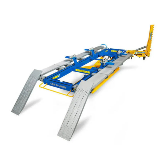
- Page 1 Quick 42 The multifaceted bench repair system Instruction Manual (40724, rev 8) 2017-09 EN...
- Page 2 Car-O-Liner shall in no event be liable for any loss or all experience with your new Car-O-Liner product. Any damage to revenues, profits or goodwill or other special,...
- Page 3 Quick 42 Car-O-Liner Group AB This Quick 42 Instruction Manual describes two different Power Unit versions, henceforward reffered to as "Type 1" and "Type 2" in this Instruction Manual. Type 2 Power unit Type 1 Power unit For identification of Type 2, see design and name plate.
- Page 4 Car-O-Liner Group AB Quick 42 This Quick 42 Instruction Manual describes two different Pendant station versions, henceforward reffered to as "Type 1" and "Type 2" in this Instruction Manual. Type 2 Pendant station Type 1 Pendant station For identification of Type 2, see design and For identification of Type 1, see design and control panel.
- Page 5 Car-O-Liner Group AB Conformity with directives and standards The Quick 42 bench repair system is manufactured by Car-O-Liner AB, which is an ISO 9001:2008 and ISO 14001:2004 accredited organisation. Below an example of how the EC Declaration of Conformity for the Quick 42 is outlined.
-
Page 6: Table Of Contents
Connection of electrical and air supply .......... 21 Bleeding of the hydraulic system ........... 22 Quick 42 With Lift ................23 3.2.1 Drive-on Ramps ..............23 3.2.2 Roll-off stops ............... 24 ... - Page 7 Quick 42 Car-O-Liner Group AB Draw aligner Q16 ................41 3.6.1 Preparations before starting alignment ....... 42 Transport and inspection of delivery ........... 42 3.7.1 Transport Protection ............43 3.7.2 Mains Connections Check ........... 43 ...
- Page 8 Car-O-Liner Group AB Quick 42 Troubleshooting ............82 General ....................82 Problem: The lift can not be raised ............. 82 Problem: The lift drops ................ 83 Problem: The lift cannot be lowered ........... 83 ...
-
Page 9: Introduction
1 Introduction General Quick 42 is used for vehicle alignment and has mobility, automatic tilt, pulling power integrated and a variably adjusted scissors lift which can raise the bench frame to the maximum working height of 1 480 mm (58 in). -
Page 10: Marking
Marking The name plate is located at the base frame of the lift. Figure 1.2 The Quick 42 name plate. The power unit name plate is located on the front of the power unit from serial no. Q61116065. (Name plate location up to serial no. Q6116064, see page 3.) Figure 1.3... -
Page 11: Safety
Great effort has been placed on the design and manufacture of Quick 42 in order for it to comply with all applicable safety aspects for this type of equipment. - Page 12 Car-O-Liner Group AB Quick 42 The following warnings and important notices are used in the instruction manual: WARNING Warning (in bold type) is used in this manual to indicate a possible danger that could lead to personal injury. An instruction is normally given, followed by a short explanation plus the possible effect if the instruction is not followed.
- Page 13 Quick 42 Car-O-Liner Group AB WARNING! Before moving the draw aligner, always lock the arm in an upright position. Risk for tipping. WARNING! Ensure that the rear crush guard is fitted so that it always drops down of its own weight and does not jam. Risk of crushing injuries.
- Page 14 Car-O-Liner Group AB Quick 42 WARNING! Observe high standards of cleanliness when working with the hydraulic system. Dirt in the hydraulic oil can cause operating problems. WARNING! Never drive the car onto the bench with the lift in raised position. Risk for vehicle overturning which may cause injuires.
- Page 15 WARNING! Maximum hydraulic jack lifting capacity t is 900 kg (2000 lbs). Risk of personal injuries and material damage. IMPORTANT! Exercise care when transporting Quick 42. IMPORTANT! When an air wrench is used to tighten nuts and bolts, ensure that it is set to a maximum of 200 Nm to avoid damage to the equipment.
-
Page 16: Safety Signs
Car-O-Liner Group AB Quick 42 Safety signs Undamaged safety signs shall always be affixed at the indicated places (see section 2.3.1 "Placement of safety signs"). If any signs are damaged or miss- ing, the user is responsible for their immediate replacement. The following... - Page 17 Quick 42 Car-O-Liner Group AB COMMAND Safety glasses must be used when hammering in the locking wedge Part No 35721 (kit) COMMAND Part No 35721 (kit) The locking pegs must always be pressed in completely. TILTING OPERATION DECAL Part No 44307 (kit)
-
Page 18: Placement Of Safety Signs
Car-O-Liner Group AB Quick 42 2.3.1 Placement of safety signs The safety signs are placed as follows: Part No 41642 Part No 41642 Part No 41642 Part No 44307 Part No 44307 Part No 40372 Figure 2.3.1 Placement of safety signs and tilting operation decal. - Page 19 Quick 42 Car-O-Liner Group AB Figure 2.3.1 Placement of safety signs on the draw aligner. Part no, see 2.3 40724, EN - rev. 8, 2017-09...
-
Page 20: Safety Devices
500 mm (20 in) from the floor, a safety latch prevents the lift from sink- ing more than a maximum of 100 mm (4 in) in the event of leakage. Quick 42 have a crush guard to prevent feet from being caught between the bench and the floor during tilting operations. -
Page 21: Installation
Quick 42 Car-O-Liner Group AB 3 Installation Connection of electrical and air supply Connect the provided plug (not provided for the single phase units) of the Q42 power unit to a receptable. Use a suitable plug for installation of the single phase unit. -
Page 22: Bleeding Of The Hydraulic System
Car-O-Liner Group AB Quick 42 Bleeding of the hydraulic system Bleeding at the satellite is recommended when installing a new system. At new installations and to avoid pushing air into the hydraulic system, connect the 2 standard hoses to the rear satellite connection of the bench. -
Page 23: Quick 42 With Lift
Quick 42 Car-O-Liner Group AB Quick 42 With Lift The bench frame is made of a welded HS square section. The top face is milled and equipped with tracks for fitting bench mountings and pulling components. On the underside there are legs upon which the bench frame rests in its low- est position as well as bench supports for the draw aligner position. -
Page 24: Roll-Off Stops
Car-O-Liner Group AB Quick 42 3.2.2 Roll-off stops WARNING! The roll-off stops should always be correctly fitted to the bench. Risk of driving off the bench and cause improper weight distribution. NOTE! The roll-off stop must be mounted for left and right hand side. -
Page 25: Crush Guard
Quick 42 Car-O-Liner Group AB 3.2.4 Crush Guard The crush guard is designed with a hinge mechanism. WARNING! Ensure that the crush guard is fitted so that it always drops down of its own weight and does not jam. Risk of crushing injuries. -
Page 26: Hydraulic Jacks Q170, 2 Pcs
The accompanying illustration shows a toothed segment fitted to the base bracket. Special chassis clamps are available for some vehicles. Consult the Car-O-Liner data sheet for a list of vehicles concerned. 3.2.10 Sill Support B23 Used to avoid damage to the sill edge when setting up the vehicle. -
Page 27: Lift And Power Unit
Quick 42 Car-O-Liner Group AB Lift and Power unit 3.3.1 Applications The scissors lift is designed solely to lift the bench system and vehicle. The maximum permitted vehicle weight is 3 000 kg (6 600 lbs). The lift consists of two main components: ... -
Page 28: Type 1 Power Unit
Car-O-Liner Group AB Quick 42 3.3.3 Type 1 Power unit The power unit is placed inside the scissors lift. The power unit has two pur- poses: Lifting the frame and vehicle with full hydraulic flow. Supply the draw aligner and the hydraulic jacks with a reduced hydraulic flow. -
Page 29: Type 1 Power Unit - Electrical Supply
Quick 42 Car-O-Liner Group AB 3.3.4 Type 1 Power unit - Electrical supply The electrical equipment is delivered for any of the following voltages: 110V, 60 Hz, single-phase 230V, 50 Hz, 3-phase 400V, 50 Hz, 3-phase WARNING! All electrical connections must be carried out by authorized personnel. -
Page 30: Electrical Diagram For 110V Ac, Single-Phase For Type 1 Power Unit
Car-O-Liner Group AB Quick 42 3.3.6 Electrical diagram for 110V AC, single-phase for Type 1 Power unit Contactor Transformer Fuse 2,5 A (glass tube fuse) 40724, EN- rev. 8, 2017-09... -
Page 31: Electrical Diagram For 110V Ac (Single-Phase) And 230/400V
Quick 42 Car-O-Liner Group AB 3.3.7 Electrical diagram for 110V AC (single-phase) and 230/400V AC (3-phase) (for 24V low voltage circuit) for Type 1 Power unit Emergency stop button Raising relay, scissors lift 3 step switch Accessory relay Lowering relay, scissors lift... -
Page 32: Type 2 Power Unit
Car-O-Liner Group AB Quick 42 3.3.8 Type 2 Power unit The power unit is placed inside the scissors lift. The power unit has two pur- poses: Lifting the frame and vehicle with full hydraulic flow. Supply the draw aligner and the hydraulic jacks with a reduced hydraulic flow. -
Page 33: Type 2 Power Unit - Electrical Supply
Quick 42 Car-O-Liner Group AB 3.3.9 Type 2 Power unit - Electrical supply The electrical equipment is delivered for any of the following voltages: 230/400V, 50 Hz, 3-phase WARNING! All electrical connections must be carried out by authorized personnel. Risk for electric shock. -
Page 34: Connection Of Motor Block, 230/400V
Car-O-Liner Group AB Quick 42 3.3.11 Connection of motor block, 230/400V 3.3.12 Electrical diagram for 24V low voltage circuit S1 Emergency stop button F2 Thermal fuse (motor) YV1 Solenoid valve SDV1 S2 Key lock switch K1 Contactor 24VAC YV2 Solenoid valve SCV1... -
Page 35: Type 1 Pendant Station
Quick 42 Car-O-Liner Group AB 3.3.13 Type 1 Pendant station How to operate the lift; see section 4.2 “Operating the lift” The pendant station consists of 4 buttons: Emergency breaker (lockable with a key). 3-step switch: A - Left position: Manoeuvring of accessories, draw aligner and hydraulic jacks. -
Page 36: Installation Of Pendant Station Cable For Type 2 Power Unit
Car-O-Liner Group AB Quick 42 Installation of pendant station cable for type 2 power unit To prevent the pendant station cable from accidently being twitched out of the Power unit, and thereby damaging the cable and contact, a cable pulling stop (art. no 45629) is included at delivery. - Page 37 Quick 42 Car-O-Liner Group AB 3. Disconnect the cable from the Power unit. Insert the cable through the hole in the base frame (opposite side from the wall power outlet) and connect it to the Power unit. 4. With the bench still at maximum height, fix the cable pulling stop to the cable just inside the hole in the base frame.
-
Page 38: Hydraulics
Car-O-Liner Group AB Quick 42 Hydraulics Central satellite locations for hydraulics and air supply. (Quick couplings) 3.5.1 Hydraulic diagram, 110V for Type 1 Power unit Spot valve Schematic hydraulic diagram, 110V, for Type 1 Power unit 40724, EN- rev. 8, 2017-09... -
Page 39: Hydraulic Diagram, 230/400V For Type 1 Power Unit
Quick 42 Car-O-Liner Group AB 3.5.2 Hydraulic diagram, 230/400V for Type 1 Power unit Schematic hydraulic diagram, for 230/400V, Type 1 Power unit SCV1 Control valve lift SCV2 Control valve accessories SDV1 Directional valve lift SDV2 Directional valve accessories CV-01 Non return valve accessories... -
Page 40: Hydraulic Diagram, 230/400V For Type 2 Power Unit
Car-O-Liner Group AB Quick 42 3.5.3 Hydraulic diagram, 230/400V for Type 2 Power unit Schematic hydraulic diagram, 230/400V, for Type 2 Power unit 1. SCV1 Control valve lift 2. SCV2 Control valve accessories 3. SDV1 Directional valve lift 4. SDV2 Directional valve accessories 5. -
Page 41: Draw Aligner Q16
Quick 42 Car-O-Liner Group AB Draw aligner Q16 The draw aligner can be placed at any position along the four sides of the base frame. It is secured to the base frame with the locking wedge (1). The draw aligner rotates sideways and is locked in the desired position with a horizontal locking peg (2). -
Page 42: Preparations Before Starting Alignment
Clean the area on the vehicle to which the clamp is to be fastened in order to ensure a good grip. Always use an approved pull chain from Car-O-Liner and see that the clamp, hook or plate is in good shape. -
Page 43: Transport Protection
Car-O-Liner Group AB 3.7.1 Transport Protection All models of Quick 42 are equipped with transport protection that holds the base frame against the bottom of the bench. IMPORTANT! Remove transport protection before the lift is put in use; otherwise damage can occur. - Page 44 Car-O-Liner Group AB Quick 42 IMPORTANT! It is the responsibility of the owner (user) of the equipment to ensure that inspection is, in accordance with current local regulations, carried out before the lift is put into use. Example of space requirements 1,9 m (73 ¾...
- Page 45 Quick 42 Car-O-Liner Group AB NOTE! When doing service and maintenance to the power unit, the recommendation is to have the bench in the tilted position! WARNING! During all service and fitting work, the lift must be blocked up while in the raised position to prevent accidental lowering. Risk of crushing injuries.
-
Page 46: Anchoring To The Floor
Quick 42 3.8.1 Anchoring to the floor Quick 42 standard configurations can either be anchored to the floor or mo- bile, see Mobile unit chapter 5. The recommendation is to anchor the lift to the floor for best performance. Also applicable local regulations may require that the lift is anchored to the floor with expander bolts. -
Page 47: Operation
Quick 42 Car-O-Liner Group AB 4 Operation General WARNING! During setup of the vehicle on the bench, care must be exercised so that the vehicle does not roll or slide out of the supports or mountings. Risk of crushing injuries. -
Page 48: Operating The Lift
Car-O-Liner Group AB Quick 42 Operating the lift Pendant station type 1: The Hand control consists of 4 buttons: Emergency breaker ( lockable with a key) 3-step switch A - Left position: Manoeuvring of accessories, draw aligner and the hydraulic jacks. -
Page 49: Tilting The Bench, Type 1 Pendant Station
Quick 42 Car-O-Liner Group AB 4.2.3 Tilting the bench, Type 1 pendant station When the bench is in its lowest horizontal position (draw aligner height), the bench can automatically be tilted. Turn the switch to its middle position Press the down button, and the bench tilt the drive-on side. -
Page 50: Raising The Bench, Type 2 Pendant Station
Car-O-Liner Group AB Quick 42 Pendant station type 2: The pendant station consists of 5 buttons: Emergency breaker. Push to activate, turn to release. Safety lock. 2-step Up button or pulling with the draw aligner. 2-step Down button or retraction of draw aligner. -
Page 51: Lowering The Bench, Type 2 Pendant Station
Quick 42 Car-O-Liner Group AB 4.2.5 Lowering the bench, Type 2 pendant station Place the switch to the upper position. If the lift is standing on the mechani- cal latch, the lift must first be raised approx. 10 mm before the down button is fully depressed. -
Page 52: Measuring System
Car-O-Liner Group AB Quick 42 Measuring system Install the Car-O-Tronic measuring bridge to the bench. 40724, EN- rev. 8, 2017-09... -
Page 53: Ramp Support And Side Ramps
Quick 42 Car-O-Liner Group AB Ramp support and Side ramps The ramp supports can be mounted in different combinations depending on wheelbase of the vehicle that will be repaired. There are three types of ramp supports: Front Middle ... - Page 54 Car-O-Liner Group AB Quick 42 There are three types of ramps: Long, 4+4 pcs Short, 2+2 pcs Drive-on ramps, 2 pcs The ramps and ramp supports may be removed when necessary to facilitate access during measurement and alignment work. The picture below shows the standard start configuration.
- Page 55 Quick 42 Car-O-Liner Group AB NOTE! The drive-on ramps must be fitted into the correct slots of the ramp supports to align with the side ramps. There are three positions for the 300 mm side ramps and two positions for the 400 mm side ramps (see previous page).
-
Page 56: Connect The Q16 To The Benchframe
Car-O-Liner Group AB Quick 42 Connect the Q16 to the benchframe The head of the drawbar must be horizontal. The wedge (B) and safety plate should hang straight down with the drawbar pushed against the safety plate (A). The supports legs of the bench frame must be adjusted so that the head of the draw aligner is free when the draw aligner is pushed in under the bench frame. -
Page 57: Positioning And Linking The Draw Aligner
When a pulling chain is delivered from Car-O-Liner together with the Q16, a safety wire is included which is to be fastened between the vehicle and the draw clamp. -
Page 58: Drive On To Q42
Car-O-Liner Group AB Quick 42 Correct positioning of the draw aligner minimizes the number of times it must be moved during the course of the work. IMPORTANT! To obtain maximum performance and to avoid damage to the draw aligner, the chain must run parallel to the hydraulic cylinder. -
Page 59: Setting Up The Vehicle
Quick 42 Car-O-Liner Group AB Drive or winch the car on to the bench. Before drive on to the bench make sure width positions of the ramps are fitted to wheel track of the vehicle. Apply the hand brake. Winch Place the car lengthwise depending of the damaged area. -
Page 60: Setup With Chassis Clamps
Car-O-Liner Group AB Quick 42 4.7.1 Setup with chassis clamps Depending upon the type of vehicle and the nature of the damage, the hy- draulic jacks shall be placed under a strong part of the body. Unibody The recommendation is to lift the vehicle with a pair of jacks at the front un- der the suspension cradle and then repeat the same procedure at the rear. - Page 61 Quick 42 Car-O-Liner Group AB NOTE! Make sure the cam lock is fully rotated before tightening. Attach the hydraulic hoses between the jacks and the power supply. 40724, EN - rev. 8, 2017-09...
-
Page 62: Using Q201 Spacers (Optional)
Car-O-Liner Group AB Quick 42 4.7.2 Using Q201 spacers (optional) When lifting a full frame vehicle or any vehicle with high lifting points (for example when using T48 Support stand), Q201 Spacers can be used. To achieve as much lifting height as possible it is necessary to close the gap between lifting pad and lifting point. - Page 63 Quick 42 Car-O-Liner Group AB Raising the hydraulic jacks WARNING! Always be extremely careful when working with jacks or hydraulic equipment. Risk for falling or flying objects. WARNING! Maximum static load per hydraulic jack = 900 kg (2 000 lbs).
- Page 64 Car-O-Liner Group AB Quick 42 Move the hydraulic jacks to the other end of the vehicle and repeat the pro- cedure. Tighten all the clamp plates to the bench mountings. Tighten the chassis clamps, first against the sill edge and then against the bench mounting.
-
Page 65: Bench Mounting
Quick 42 Car-O-Liner Group AB 4.7.3 Bench Mounting Please note that there are different types of bench mountings. If the vehicle is damaged so that it does not lie correctly in one or more of the chassis clamps, the following procedure is recommended: ... -
Page 66: Q62 Quick Setup
Car-O-Liner Group AB Quick 42 Thighten all bolts and nuts. Repeat the procedure on the other fixation point. 4.7.5 Q62 Quick setup When using two Q62 it’s easy to mount without jacking up the car. Depend- ing of the damage, Q63 could be mounted on the same side or the opposite side. - Page 67 Quick 42 Car-O-Liner Group AB Tighten the bolts for EVO tower. Mount the other EVO tower in the same order. 40724, EN - rev. 8, 2017-09...
-
Page 68: Set Up Of A Vehicle Without Front Or Rear Sub Frame
Car-O-Liner Group AB Quick 42 Set up of a vehicle without front or rear sub frame Illustrations show the recommended way to set up the vehicle. WARNING! It is forbidden to use the T48 on top of the drive on ramps. -
Page 69: Q16 Draw Aligner
Quick 42 Car-O-Liner Group AB Q16 Draw aligner Turn the Switch in “Lift” position. Push the “down” button to lowering the lift. Keep the button pushed down until the lift reaches draw aligner height. Release the button. Position the draw aligner in desired position. -
Page 70: Pulling Straight Forward When Two Fixing Points Are Used
Car-O-Liner Group AB Quick 42 4.9.2 Pulling straight forward when two fixing points are used Mount the clamp’s on the same side as the damage/draw aligner. Place the draw aligner from the side to avoid interference with the hydraulic hose. -
Page 71: Useful When Working With The Vehicle
Quick 42 Car-O-Liner Group AB 4.10 Useful when working with the vehicle 4.10.1 Compressed air Air tools could easily be connected to the compressed air outlet on the bench. 4.10.2 Hand tools The drive on ramp’s can be used for placing the hand tools or other equip- ment during the repair. - Page 72 Car-O-Liner Group AB Quick 42 WARNING! Maximum height when using ramps as standing platform is 1 meter. 40724, EN- rev. 8, 2017-09...
-
Page 73: Mobile Unit
Quick 42 Car-O-Liner Group AB 5 Mobile unit General WARNING! The floor underneath the bench with wheels must be level. When not moving the bench, always set the wheel brakes. Risk of unintentional rolling. WARNING: Risk of rolling bench. The wheel assemblies shall be locked after the bench has been moved. - Page 74 Car-O-Liner Group AB Quick 42 6. Install the jacking plate at the end of the bench. Lift the bench, minimum 55 cm (22 in) using a trolley jack placed underneath the jacking plate. 7. Install the transport wheels on the bench sides using the second position of the console holes.
-
Page 75: Installation Of Transport Wheels, Using Hydraulic Jacks
Quick 42 Car-O-Liner Group AB Installation of transport wheels, using hydraulic jacks IMPORTANT! Transport protection must be used whenever the equipment is moved. Transport Protection 1. Raise the bench to a suitable safety latch stop level. 2. Turn-up the bench supports, use a circlip plier. - Page 76 Car-O-Liner Group AB Quick 42 the second position of the console holes (see 5.2, step 7). Make sure that the locking peg fits in the hole of the bench. 8. Lower the hydraulic jacks until the wheels stand on the floor.
-
Page 77: Safety
Quick 42 Car-O-Liner Group AB over high obstacles e. g doorpost, you need to lift the bench in order to not destroy the wheels. Safety 5.4.1 Two Q16 on the same bench side on an empty unbolted bench Normally, when a bench is bolted to the floor, there are no problems to con- nect two Q16 draw aligners on the same bench-side of an empty bench. - Page 78 Car-O-Liner Group AB Quick 42 By observing and following the safety precautions, users of the Quick 42 will ensure safer working conditions for themselves and their fellow work- ers. 40724, EN- rev. 8, 2017-09...
-
Page 79: Service And Maintenance
Quick 42 Car-O-Liner Group AB 6 Service and Maintenance General warnings WARNING! During all service and fitting work, the lift must be blocked up while in the raised position to prevent accidental lowering. Risk of crushing injuries. WARNING! All work on the electrical equipment must be carried out by qualified personnel. -
Page 80: Bench Inspection And Service Plan
Car-O-Liner Group AB Quick 42 Bench inspection and service plan Daily inspection Monthly inspection Check function of the limit switch (controls draw aligner height and foot crush protection) Check that the safety latch drops easily into its slot. ... -
Page 81: Draw Aligner Inspection And Service Plan
Quick 42 Car-O-Liner Group AB Draw aligner inspection and service plan The draw aligner and its component parts are subject to large amounts of loading and strain and therefore need regular inspection and replacement of any worn parts. For the hydraulic components, please see the manufacturer’s instructions. -
Page 82: Troubleshooting
Car-O-Liner Group AB Quick 42 7 Troubleshooting General The trouble shooting instructions in this chapter will help you to quickly find and correct the most common faults that may occur when using the Car-O- Liner Power unit. WARNING! All electrical connections must be carried out by authorized personnel. -
Page 83: Problem: The Lift Drops
Quick 42 Car-O-Liner Group AB The motor runs, but the 8. Defective relief valve Connect a pressure gauge to the hydraulic hose and lift cannot be raised check the pressure (should be 30 Mpa). Pressure is set at the factory; if the pressure is incorrect, contact your supplier. -
Page 84: Emergency Lowering Of The Lift, Earlier Design Of Sdv 1 Valve
Car-O-Liner Group AB Quick 42 7.5 Emergency lowering of the lift, earlier design of SDV 1 valve Cut off power to the bench. Place safety supports in front and rear of the bench between floor and bench, eg. pallets or jackstands. - Page 85 Quick 42 Car-O-Liner Group AB Mount the plastic nut. Place special tool no 44116 on the nut. Press down and lock. Tighten the whole assembly as far as possible. Make sure that the centre screw M4 is fully in. If the security latches are in unlocked position, raise the security latches and insert a guide (card board or masonite) to prevent the security latches from attaching.
- Page 86 Car-O-Liner Group AB Quick 42 When the brass screw is loosened the lift is slowly lowered all the way to tilted position (make sure that the car can not roll off when wheels are mounted) The limit switch for tilting position will not be engaged when carrying out this operation.
- Page 87 Quick 42 Car-O-Liner Group AB If the security latches are in locked position by the weight of the bench, they must first be loosened by lifting the bench with two hydraulic cylinders and pumps, to enable the security latches to come off.
-
Page 88: Emergency Lowering Of The Lift, Later Design Of Sdv 1 Valve
Car-O-Liner Group AB Quick 42 7.6 Emergency lowering of the lift, later design of SDV 1 valve Cut off power to the bench. Place safety supports in front and rear of the bench between floor and bench, eg. pallets or jackstands. - Page 89 Quick 42 Car-O-Liner Group AB Apply special tool no 44110. Tighten the special tool. If the security latches are in unlocked position, raise the security latches and insert a guide (card board or masonite) to prevent the security latches from attaching. If in locked position, see step 12-15.
- Page 90 Car-O-Liner Group AB Quick 42 When the brass screw is loosened the lift is slowly lowered all the way to tilted position (make sure that the car can not roll off when wheels are mounted) the micro breaker for tilting position is disconnected when carrying out this operation.
- Page 91 Quick 42 Car-O-Liner Group AB If the security latches are in locked position by the weight of the bench, they must first be loosened by lifting the bench with two hydraulic cylinders and pumps, to enable the security latches to come off.
-
Page 92: Dismantling And Salvage
Car-O-Liner Group AB Quick 42 8 Dismantling and Salvage IMPORTANT! For the sake of the environment, it is important that the equipment is dismantled in an environmentally friendly way. Mechanical Components When scrapping or dismantling lift components the oil must be emptied from the cylinder, hoses and pump. -
Page 93: Technical Specifications
Quick 42 Car-O-Liner Group AB 9 Technical Specifications Bench length 4 200 mm (165 in) Ramp length 4 200 mm (165 in) Bench width 1 110 mm (47.3 in) Bench width with ramps: minimum 1 590 mm (62.6 in) maximum... -
Page 94: Spare Parts
Car-O-Liner Group AB Quick 42 Spare parts The spare parts required for maintaining the Car-O-Liner Quick 42 are listed in this chapter. For other spare parts and questions about repair of the Power Unit, please contact the service department at Car-O-Liner AB. - Page 95 Quick 42 Car-O-Liner Group AB Figure 10.1 Bench spare part kits 40724, EN - rev. 8, 2017-09...
-
Page 96: Type 1 Power Unit - Summary
Car-O-Liner Group AB Quick 42 10.2 Type 1 Power unit - summary Position Quantity Part No. Object See section Remote pendant 10.2.1 43608 Motor 110V 1 PH 60 Hz 43609 Motor 230/400V 3 PH 50Hz Pump unit 400V Q42 See section 10.2.2... - Page 97 Quick 42 Car-O-Liner Group AB Figure 10.2 Type 1 Power unit - summary 40724, EN - rev. 8, 2017-09...
-
Page 98: Type 1 Pendant Station
Car-O-Liner Group AB Quick 42 10.2.1 Type 1 Pendant station Position Quantity Part No. Object 43511 Stop with key 43648 Control switch label 43509 Switch button Complete pendant with cable 41389 Block for emergency stop 43514 Block for switch button 43516 Block "1-speed"... -
Page 99: Type 1 Pump Unit 400/440V
Quick 42 Car-O-Liner Group AB 10.2.2 Type 1 Pump unit 400/440V Position Quantity Part No. Object 33124 Tank with cover 8L 43529 Flow control valve A2 43529 Flow control valve A1 43533 Pump 400V, Q42 with pipe and filter 44245... -
Page 100: Type 1 Pump Unit 110V
Car-O-Liner Group AB Quick 42 10.2.3 Type 1 Pump unit 110V Position Quantity Part No. Object 33124 Tank with cover 8L 43529 Flow control valve A2 43529 Flow control valve A1 43531 Pump 110V, Q42 with pipe and filter Valve SCV 1... -
Page 101: Type 1 Upper Manifold
Quick 42 Car-O-Liner Group AB 10.2.4 Type 1 Upper manifold Position Quantity Part No. Object 44003 Adapter between manifolder and block 44004 O-ring for adapter 33985 Valve SCV 2 Coil SCV 2 33945 Connector 43523 Valve and coil kit SDV 1 & 2... -
Page 102: Type 1 Electrical Components
Car-O-Liner Group AB Quick 42 10.2.5 Type 1 Electrical components Position Quantity Part No. Object 44233 Fuse 2,5A , 5x20 mm 43611 Relay 43613 Contactor 400V Contactor 110V 43612 Transformer 230/400V 43614 Transformer 110V 43615 Pneumatic valve 43616 Figure 10.7 Type 1 Electrical components 40724, EN- rev. -
Page 103: Type 2 Power Unit - Summary
Quick 42 Car-O-Liner Group AB 10.3 Type 2 Power unit – summary Position Quantity Part No. Object See section Pendant station 10.2.1 43609 Motor 230/400V 3 PH 50Hz Pump unit 400V Q42 See section 10.2.2 Pneumatic valve 46510 Upper manifold Q42 See section 10.2.4... - Page 104 Car-O-Liner Group AB Quick 42 Figure 10.8 Type 2 Power unit - summary 40724, EN- rev. 8, 2017-09...
-
Page 105: Type 2 Pendant Station
Quick 42 Car-O-Liner Group AB 10.3.1 Type 2 Pendant station Position Quantity Part No. Object Pendant complete with cable 45899 Pendant complete without cable 45918 Cable with connector 46473 Cable pulling stop 46529 Figure 10.9 Type 2 Pendant station 40724, EN - rev. 8, 2017-09... -
Page 106: Type 2 Pump Unit 400V
Car-O-Liner Group AB Quick 42 10.3.2 Type 2 Pump unit 400V Position Quantity Part No. Object Valve SCV 1 46472 Coil SCV 1 33945 ATTENTION! New type of valve and coil (below) are implemented from serial no: 61117065, see nameplate. -
Page 107: Type 2 Upper Manifold
Quick 42 Car-O-Liner Group AB 10.3.3 Type 2 Upper manifold Position Quantity Part No. Object Coil SCV /SDV 42242 Valve SDV 1/2 42239 O-ring kit SDV Valve 46555 O-ring kit SCV Valve 46554 46472 Valve SCV 2 Emergency tool 44110 Figure 10.11 Type 2 Upper manifold... -
Page 108: Type 2 Upper Manifold (From Serial No 61117065, See Nameplate!)
Car-O-Liner Group AB Quick 42 Type 2 Upper manifold (from serial no 61117065, see nameplate!) Position Quantity Part No. Object Coil SCV /SDV 48426 Valve SDV 1/2 48429 O-ring kit SDV Valve 46555 O-ring kit SCV Valve 46554 48425 Valve SCV 2... -
Page 109: Type 2 Electrical Components
Quick 42 Car-O-Liner Group AB 10.3.4 Type 2 Electrical components Position Quantity Part No. Object 44233 Fuse 2,5A , 5x20 mm 46505 PCB Complete 44236 Contactor 400V Transformer 230-400/24V 44235 Transformer 440-460/24V 46912 Pneumatic valve with coil, see section 3.3.8 46510 Position switch, see section 3.3.8... -
Page 110: Draw Aligner Q16
Car-O-Liner Group AB Quick 42 10.4 Draw aligner Q16 Position Quantity Part No. Object 30952 Wheel 39845 Wheel 142383N 30312 Wire Connecting Rod 30408 Lock washer 30358 Wedge 30326 Peg Ø24 30334 Q161 Cylinder Q16 39756 Seal kit Q16 44366... -
Page 111: Ramps
Quick 42 Car-O-Liner Group AB 10.5 Ramps Position Quantity Part No. Object 42723 Console welded drive on left 42717 Console welded drive on right 41448 Console welded Roll-off stop front 36891 Drive-on ramp (width 300 mm) 41079 Drive-on ramp (width 400 mm) - Page 112 Car-O-Liner Group AB Quick 42 40724, EN- rev. 8, 2017-09...
- Page 113 Profitable Alignment Processes to the Automotive Industry, including Technical Development, Training and Service. Over 55 000 Car-O-Liner Collision Repair Systems are in use worldwide. Car-O-Liner runs operations of its own in Scandinavia, USA, UK, France, Germany, Singapore, India and China and sells through local distributors in more than 60 countries.
Need help?
Do you have a question about the Quick 42 and is the answer not in the manual?
Questions and answers