
Related Manuals for CBS ArcSafe RRS-2


Summary of Contents for CBS ArcSafe RRS-2
- Page 1 CBS ArcSafe® RRS-2 (Remote Racking System) P.O. Box 550 Argyle, TX 76226 (940) 382-4411 www.CBS ArcSafe.com...
- Page 2 A remote switch operator is the power and control console for service personnel to remotely charge, close, and trip circuit breakers from a safe distance using a CBS ArcSafe® RSA. The RSO can be used in conjunction with the CBS ArcSafe® remote racking system for complete charge, close, trip, and racking operations or independently as a stand-alone device for use with a remote racking system.
-
Page 3: Table Of Contents
3.2 Unpacking the RRS-2 ..................... 11 3.3 Charging the RRS-2 ......................12 3.4 Setting the Actuator Limit Switches................13 3.5 Setting up the RRS-2 for Operation ................14 3.6 Current Control Module (CCM) Configuration ............. 15 3.6.1 Manual Current Control Configuration ................15 3.6.2 Automatic Current Control Configuration ................ - Page 4 2.0 Camera System Set-up ....................32 3.0 Camera System Operation .................... 32 4.0 Camera Troubleshooting Guide ..................33 Appendix D: Radio Remote PS..................35 1.0 Components ........................35 2.0 Radio Remote Models ....................36 3.0 Button Configurations ....................37 RRS-2 Technical Manual...
- Page 5 DANGER! *Ensure that switchgear is properly maintained and in good working order before using the RRS-2 on your switchgear. Contact your local group CBS service provider at www.gcbs.com to assist in proper care and maintenance for your switchgear. P.O. Box 550...
-
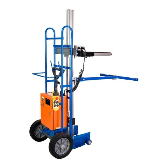
Page 6: Description
(Fig. 3) designed to quickly secure the cubicle brace and the RRS-2 to the cubicle. Tooling (Fig. 1.5) – The RRS-2 tooling is custom built for every breaker and allows for the RRS-2 to attach to a variety of breakers simply by swapping out the tooling. Typically, the main actuator racks the circuit breaker while the secondary actuator depresses the circuit breaker interlocks although this may differ depending on the breaker and switchgear being repositioned. - Page 7 3. Slide Rail Locks 6. Cubicle Brace 9. Transportation and Stability Wheels Figure 1.1 – Structural Assembly Floor Locks (optional) Stabilizers (optional) Figure 1.2 – RRS-2 Floor Locks and Stabilizers (optional) RRS-2 Technical Manual ® © 2010 CBS ArcSafe 2012-04-18...
- Page 8 The stabilizers help to prevent the RRS-2 from tilting backwards during operation. Stair Climber Rails *optional (Fig. 1.3) – The stair climbers allow for the RRS-2 to easily be moved up/down stairs and in/out of vehicles. Pneumatic Tires *optional (Fig. 1.4) – The RRS-2 may be equipped with optional pneumatic tires in order for the RRS-2 to easily travel over gravel or other rough surfaces.
- Page 9 Figure 1.3 – RRS-2 Stair Climber Rails (optional) Figure 1.4 – RRS-2 Pneumatic Tires (optional) RRS-2 Technical Manual ® © 2010 CBS ArcSafe 2012-04-18...
- Page 10 Siemens Type MA, Foot-Pedal Interlock Figure 1.5 – Interlock Actuators and Tooling ATTENTION These are only two interlock actuators and tooling of many designs that are available. Every RRS-2 tooling accessory is custom built for your switchgear. RRS-2 Technical Manual ®...
-
Page 11: Control Assembly
They both use an internal clutch to limit force available to prevent over racking. The actuator attaches to the RRS-2 via the slide rail, and can easily be repositioned with the lever locks (Fig. 2-4). Secondary Actuator (Fig. 1.5) – The secondary actuator is generally used on the circuit breakers interlocks and supplies the driving force needed to engage circuit breaker interlock devices which are normally actuated manually by the operator. -
Page 12: Controls And Indications
Lights Control Switch (Fig. 2.1.2) *optional – The light control switch operates the optional CBS ArcSafe® LED lighting system that is attached to the RRS-2. Please remember to turn the lights off when not in use. - Page 13 L ON “Distance is Safety” S OFF C ON INSTALL A OFF REMOVE DOWN MAX CURRENT www.CBS ArcSafe.com *lights and camera are OPTIONAL equipment Mounted Controls Figure 2.1 – RRS-2 Electrical Cabinet RRS-2 Technical Manual ® © 2010 CBS ArcSafe 2012-04-18...
-
Page 14: Preparation And Operation
3.1 Set up Training Included with your purchase of the RRS-2 is 4 hours of training from either a CBS ArcSafe® equipment representative or an approved CBS ArcSafe® outside representative. Please call CBS ArcSafe® at (940) 382-4411 to set up this FREE training seminar for your service personnel prior to ANY operations. -
Page 15: Unpacking The Rrs-2
3.2 Unpacking the RRS-2 The RRS-2 is placed in a protected condition to allow the unit to be shipped more efficiently and to prevent damage from occurring. Perform the following steps to unpack the RRS-2 and prepare it for operation. -
Page 16: Charging The Rrs-2
1. Rotate the power switch to the OFF position if not using the RRS-2. ATTENTION It is perfectly safe to charge the RRS-2 during operations, however if you leave the unit on while storing it the unit will pull unnecessary electricity from the outlet. -
Page 17: Setting The Actuator Limit Switches
5. Secure the limit switches by screwing back in the set screws – be EXTREMELY careful not to over tighten these screws as they are fragile, very little torque is needed in order to secure those limit switches. RRS-2 Technical Manual ® © 2010 CBS ArcSafe... -
Page 18: Setting Up The Rrs-2 For Operation
1. Ensure the RRS-2 is charged and/or the unit is plugged in to an AC power source. 2. Ensure the breaker being racked is OPEN according to manufacturer specifications. -
Page 19: Current Control Module (Ccm) Configuration
RRS-2 is in operation. If the down button is not pressed than the CCM will display the present amount of current being drawn. - Page 20 Remove the circuit breaker racking adapter and any extensions from the breaker and RRS-2. d. Turn the power switch off. Cover the RRS-2 with the dust cover or the waterproof cover (optional) and store the unit in a clean, dry location. RRS-2 Technical Manual ®...
-
Page 21: Automatic Current Control Configuration
CONNECTED position and depending on how the breaker racks the RRS-2 may also stop at the TEST position automatically. 6. When the circuit breaker racking operation is complete, the RRS-2 can be detached from the circuit breaker and stowed. RRS-2 Technical Manual ®... - Page 22 Remove the circuit breaker racking adapter and any extensions from the breaker and RRS. b. Switch the power isolation switch to the OFF position. Cover the RRS-2 with the dust cover or the waterproof cover (optional) and store the unit in a clean, dry location. RRS-2 Technical Manual ®...
-
Page 23: Automatic Current Control Time Stop Configuration
The factory default and recommended setting for normal use is .1 seconds. 3. Press either the Install or Remove buttons to exit the Time Stop editing feature, the Time Stop will be automatically saved. RRS-2 Technical Manual ® © 2010 CBS ArcSafe... -
Page 24: Operation
4.0 Operation This section describes the steps necessary to install and remove the circuit breaker using the RRS-2. 4.1 Circuit Breaker Installation These are the following requirements and steps for circuit breaker installation using the RRS-2. 4.1.1 Requirements for Installation The following installation procedure assumes that the following prerequisites have been met: 1. -
Page 25: Circuit Breaker Removal
5. Ensure the emergency stop push button is deactivated by turning the button clockwise to unlatch. 6. Use the pendant station as discussed in the given RRS-2 tooling guide. If the pendant retractile cord is not long enough for the operator to leave the arc... -
Page 26: Maintenance
5.3 After Use After use, clean the RRS-2 ensuring the power supply vents are free of dust and debris. Ensure the unit is free of oil or grease and if necessary, clean with a dry cloth. Store the device covered with either the standard dust cover or the waterproof cover (optional), in a clean, dry location to prevent damage. -
Page 27: Ordering Replacement Parts
6.0 Ordering Replacement Parts When ordering replacement parts please specify the serial number and MFD from the RRS-2 nameplate. From the RRS-2 nameplate: Nomenclature: RRS-2 Serial number MFD: RRS-2 Technical Manual ® © 2010 CBS ArcSafe 2012-04-18... - Page 28 Remote Racking Unit RRS-2 Parts List CBS ArcSafe® Item Description Part Image 2 * 12Vdc Batteries for 24 Vdc Battery Charger Power Cable Charging Light Front Wheel Door Lock RRS-2 Technical Manual ® © 2010 CBS ArcSafe 2012-04-18...
- Page 29 Remote Racking Unit RRS-2 Parts List Cont. CBS ArcSafe® Item Description Part Image 25’ Pendant Retractile Cord Extension *optional Power Switch Power Light Storage Bag PS mounted Receptacle R2/R4 Stair Climber Rails RRS-2 Technical Manual ® © 2010 CBS ArcSafe...
- Page 30 Remote Racking Unit RRS-2 Parts List Cont. CBS ArcSafe® Item Description Part Image Standard Tires Pneumatic Tires *Recommended for rough terrain RRS-2 Technical Manual ® © 2010 CBS ArcSafe 2012-04-18...
-
Page 31: Appendix A: Specifications
High Lift – The high lift system, when installed allows for the RRS-2 to rack/unrack breakers that are up to 90” high, although depending on the application needs some high lift systems are built higher. LED Light – The LED light system attaches a light to the front of the RRS-2 in order to account for low light conditions. - Page 32 This page has been intentionally left blank. RRS-2 Technical Manual ® © 2010 CBS ArcSafe 2012-04-18...
-
Page 33: Appendix B: Troubleshooting Guide
Faulty batteries or charger. Replace faulty equipment. Contact your CBS ArcSafe® Technical Sales/ Support Agent to obtain replacement parts. The RRS-2 has been stored in Contact your CBS ArcSafe® freezing temperatures. Technical Sales/ Support Agent for solutions. The batteries have aged from Replace the system batteries. - Page 34 This page has been intentionally left blank. RRS-2 Technical Manual ® © 2010 CBS ArcSafe 2012-04-18...
-
Page 35: Appendix C: Wireless Camera System
Power Cable – The power cable charges the internal battery pack and powers the unit if AC power is available. Battery Pack (internal) – The battery pack in the wireless camera system will run for approximately 5 hours on a single charge. Available 1/15/2010 RRS-2 Technical Manual ® © 2009 CBS ArcSafe 2012-04-18... -
Page 36: Camera System Set-Up
LCD power cable into AC power. Power on the camera. The camera is located on the CBS ArcSafe® Remote Racking System; the camera is powered on by turning the ‘CAMERA’ switch located on the Remote Racking Unit Control Panel clockwise to the ON position. -
Page 37: Camera Troubleshooting Guide
AC power supply. Ensure the rechargeable power supply has an adequate charge. Ensure the A/V cable is connected to the output of the wireless receiver and the input of the LCD display. RRS-2 Technical Manual ® © 2009 CBS ArcSafe 2012-04-18... - Page 38 This page has been intentionally left blank. RRS-2 Technical Manual ® © 2009 CBS ArcSafe 2012-04-18...
-
Page 39: Appendix D: Radio Remote Ps
The radio remote pendant station is designed specifically for the system that it came with. The radio remote will NOT work with any other CBS ArcSafe® Remote System, therefore please keep the radio remote with the system that it came with. Also to limit interference please ensure that the channel numbers of units purchased at different dates differ. -
Page 40: Radio Remote Models
The power on the system will appear off until the radio remote is turned on when using your system with the PS-R6. Therefore please ensure that the pendant station is turned on before troubleshooting why the power in your system is not turning on. RRS-2 Technical Manual ® © 2009 CBS ArcSafe... -
Page 41: Button Configurations
3.0 Button Configurations REMOVE INSTALL REMOVE INSTALL REMOVE INSTALL A & B A & B PS-R6-C Figure D.2 – Possible Button Configurations RRS-2 Technical Manual ® © 2009 CBS ArcSafe 2012-04-18... - Page 42 This page has been intentionally left blank. RRS-2 Technical Manual ® © 2009 CBS ArcSafe 2012-04-18...
- Page 43 Replace the batteries inside of the remote. This may require you The radio remote’s batteries carefully removing the remote are dead. from its protective plastic cover and carefully unscrewing the back cover on the remote. RRS-2 Technical Manual ® © 2009 CBS ArcSafe 2012-04-18...
- Page 44 P.O. Box 550 Argyle, TX 76226 Tel: 940-382-4411 Fax: 940-382-9435 Website: www.CBSArcSafe.com Email: info@CBSArcSafe.com DANGER! *Ensure that personnel using this equipment are adequately trained in the operation of the switchgear they are planning to work with; that they are correctly stationed outside the arc flash boundary;...
- Page 45 *PLEASE TEAR OUT WARRANTY REGISTRATION – Products IMPORTANT: Complete and mail this warranty registration form as soon as possible. Date: RRS-2 RRS-2-BE CBS ArcSafe® Model (CIRCLE ONE): CBS ArcSafe® Serial Number: Company: Address 1: Address 2: City: State/Province: Zip/Postal Code:...
Need help?
Do you have a question about the RRS-2 and is the answer not in the manual?
Questions and answers