Table of Contents
Advertisement
Quick Links
Installation Guide for
VeeaHub™ Pro Outdoor
Version 0.3
Introduction
The VeeaHub Pro Outdoor (VHH10) is a ruggedized version of the popular VeeaHub Pro intelligent
wireless hub. The VHH10 has an IP-65 rating and is designed to be installed in outdoor environments.
This document will be your guide to the proper installation of the VHH10.
VHH10 Installation Kit
The VHH10 installation kit is packed in a separate box from the VHH10 unit itself. The installation kit
contains:
• 1 x Wall Mounting Bracket (2 pieces)
• M8 screws to attach mounting bracket to VHH10
• M8 screw to attach grounding cable
• 2 x M12 male connectors with pigtail cables for ethernet
• 1 x M12 female connector with pigtail cable for power
• 1 x Self-locking tweezers (for SD card insertion)
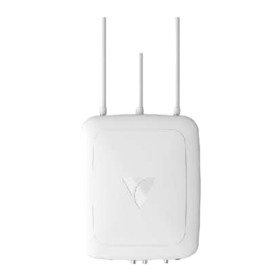
Understanding the VHH10
As you read through this document, please refer to the following diagrams to help you locate the various
connections, buttons and Indicators:
1
2
3
Figure 1
1. Lower LED
2. Upper LED
3. Power Connector (M12 male)
4. Ethernet Connector (M12 female) – this connection supports PoE
5. Ethernet Connector (M12 female)
Veea, Inc. Confidential & Proprietary
4
5
6
7
1
Advertisement
Table of Contents

Related Manuals for VEEA VeeaHub Pro Outdoor

Summary of Contents for VEEA VeeaHub Pro Outdoor
- Page 1 Version 0.3 Introduction The VeeaHub Pro Outdoor (VHH10) is a ruggedized version of the popular VeeaHub Pro intelligent wireless hub. The VHH10 has an IP-65 rating and is designed to be installed in outdoor environments. This document will be your guide to the proper installation of the VHH10.
-
Page 2: Understanding The Lights
The VHH10 unit has two ethernet ports. The port labeled #4 in Figure 1 above, accepts 802.3bt power and should be used as the primary gateway connection. The other ethernet port is an optional auxiliary Veea, Inc. Confidential & Proprietary... - Page 3 P5, DD+, White/Brown P6, DD-, Brown P7, DC-, White/Blue P8, DC+, Blue Pin 1&3 RS232/422/485 Pin1, RTS, White/Orange Serial Pin2, CTS, White/Green CAT5e Pin 2&4 Pin3, TXD, Orange Pin4, RXD, Green Pin5, GND, Brown Table 2 Veea, Inc. Confidential & Proprietary...
- Page 4 IMPORTANT: You must ensure that the unit is mounted so that the edge with the antenna connections facing UP, as shown in Fig. 3. Also make sure to orient the wall mounting bracket correctly, as shown in the diagram. Veea, Inc. Confidential & Proprietary...
-
Page 5: Grounding Connection
Figure by the large green arrow. Because it may be difficult to reach this connection after the unit is hung on the wall, it is advisable to connect the grounding lug to the VHH10 unit before hanging the unit on the wall mount. Veea, Inc. Confidential & Proprietary... -
Page 6: Wall Mounting Procedure
4. Hang the unit assembly on the wall piece of the bracket by matching up the bracket side flanges and sliding the unit assembly down onto the mounted wall piece until it rests on the locking flanges. Veea, Inc. Confidential & Proprietary... -
Page 7: Power Connections
If Using a Separate DC Power Cable Refer to Table 3 for power cable connections. When using a separate DC power cable, a minimum 14# conductor cable should be used. Maximum length is 50 feet. Sim Card Installation Veea, Inc. Confidential & Proprietary... - Page 8 Please carefully select the installation position and make sure that the final output power does not exceed the limit set force in relevant rules. The violation of the rule could lead to serious federal penalty Veea, Inc. Confidential & Proprietary...