Table of Contents
Advertisement
Quick Links
Advertisement
Chapters
Table of Contents

Related Manuals for Rosch Computer MS-98H4

Summary of Contents for Rosch Computer MS-98H4
- Page 1 MS-98H4 (v1.x) Industrial Computer Board...
-
Page 2: Revision History
Preface Copyright Notice The material in this document is the intellectual property of MICRO-STAR IN- TERNATIONAL. We take every care in the preparation of this document, but no guarantee is given as to the correctness of its contents. Our products are under continual improvement and we reserve the right to make changes without notice. -
Page 3: Safety Instructions
MS-98H4 Safety Instructions ■ Always read the safety instructions carefully. ■ Keep this User’s Manual for future reference. ■ Keep this equipment away from humidity. ■ Lay this equipment on a reliable flat surface before setting it up. ■ The openings on the enclosure are for air convection hence protects the equipment from overheating. -
Page 4: Chemical Substances Information
Preface Chemical Substances Information In compliance with chemical substances regulations, such as the EU REACH Regulation (Regulation EC No. 1907/2006 of the European Parliament and the Council), MSI provides the information of chemical substances in products at: http://www.msi.com/html/popup/csr/evmtprtt_pcm.html Battery Information European Union: Batteries, battery packs, and accumulators should not be disposed of as unsorted household waste. -
Page 5: Ce Conformity
MS-98H4 CE Conformity Hereby, Micro-Star International CO., LTD declares that this de- vice is in compliance with the essential safety requirements and other relevant provisions set out in the European Directive. FCC-A Radio Frequency Interference Statement This equipment has been tested and found to comply with the limits for a Class A digital device, pursuant to Part 15 of the FCC Rules. -
Page 6: Table Of Contents
Preface CONTENTS Copyright Notice .................... ii Trademarks ....................ii Revision History .................... ii Technical Support ..................ii Safety Instructions ..................iii Chemical Substances Information ............... iv Battery Information ..................iv CE Conformity ....................v FCC-A Radio Frequency Interference Statement ......... v WEEE Statement .................. -
Page 7: Overview
Overview Thank you for choosing the MS-98H4, an excellent industrial computer board. Based on the innovative Intel Core™ i7/i5/i3/Celeron Processor for ® ® optimal system efficiency, the MS-98H4 supports 2 SO-DIMM slots to provide up to 16GB DDR3L 1333/1600 MHz memory. -
Page 8: Motherboard Specifications
Overview Motherboard Specifications Processor ■ 5th Gen Intel Broadwell-ULT Mobile i7/i5/i3/Celeron Processor ® ® Memory ■ 2 x SO-DIMM slots, dual channel DDR3L 1333/1600 MHz ■ Up to 16GB Networking ■ 1 x Intel I218LM GbE LAN PHY ® ■ 1 x Intel I210-AT GbE LAN ®... - Page 9 MS-98H4 Rear I/O ■ 2 x DisplayPorts (1 x colay with HDMI, 1 x colay with LVDS) ■ 1 x DVI-I port (DVI-D only) ■ 2 x GbE RJ45 ports ■ 4 x USB3.0 ports ■ 1 x TPM header ■...
-
Page 10: Motherboard Layout
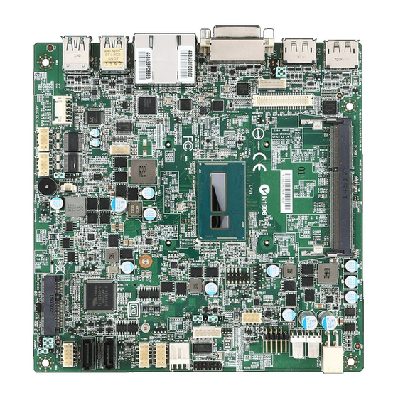
Overview Motherboard Layout LVDS Power Jumper Inverter Inverter Power Connector SO-DIMM System Power Jumper LVDS Slots (one on Connector Rear I/O Connector the backside) CPU Fan Connector System Fan Connector Front Panel Header Connector Keyboard/Mouose Connector LPC Header Clear CMOS Jumper SATA Power Connector... -
Page 11: Hardware Setup
Hardware Setup This chapter provides you with the information about hardware setup procedures. While doing the installation, be careful in holding the com- ponents and follow the installation procedures. For some components, if you install in the wrong orientation, the components will not work prop- erly. - Page 12 Hardware Setup Components Reference Guide Memory ....................2-3 Power Supply ..................2-4 DC-In Power Connector: JPWR1 ...............2-4 SATA Power Connector: JSATA_PWR1 .............2-4 Rear Panel I/O ...................2-5 Connector ..................2-6 Fan Power Connector: CPUFAN1, SYSFAN1 ...........2-6 Serial ATA Connector: SATA1, SATA2 ............2-6 GPIO Connector: JGPIO1 ................2-7 Front Panel Header: JFP1 .................2-7 Audio Amplifier Header: JSPK1 ..............2-8 Front Audio Connector: JAUDIO1 ..............2-8...
-
Page 13: Memory
MS-98H4 Memory The SO-DIMM slot is intended for memory modules. 1. Locate the SO-DIMM slot. Align the notch on the DIMM with the key on the slot and insert the DIMM into the slot. 2. Push the DIMM gently down- wards until the slot levers click and lock the DIMM in place. -
Page 14: Power Supply
Hardware Setup Power Supply DC-In Power Connector: JPWR1 This connector is used to provide power to the motherboard. SATA Power Connector: JSATA_PWR1 This connector is used to provide power to SATA devices. Important Make sure that all the power cables are securely connected to a proper power supply to ensure stable operation of the motherboard. -
Page 15: Rear Panel I/O
MS-98H4 Rear Panel I/O DisplayPorts DVI-I Port GbE RJ45 Ports USB3.0 Ports (DVI-D only) DisplayPorts DisplayPort is a digital display interface standard. This connector is used to con- nect a monitor with DisplayPort inputs. DVI-I Port (DVI-D only) The DVI-D (Digital Visual Interface-Integrated) connector allows you to connect an LCD monitor. -
Page 16: Connector
Hardware Setup Connector Fan Power Connector: CPUFAN1, SYSFAN1 The fan power connector supports system cooling fan with +12V. When con- necting the wire to the connectors, always note that the red wire is the positive and should be connected to the +12V; the black wire is Ground and should be connected to GND. -
Page 17: Gpio Connector: Jgpio1
MS-98H4 GPIO Connector: JGPIO1 This connector is provided for the General-Purpose Input/Output (GPIO) periph- eral module. Front Panel Header: JFP1 This front panel connector is provided for electrical connection to the front panel switches & LEDs and is compliant with Intel Front Panel I/O Connectivity Design... -
Page 18: Audio Amplifier Header: Jspk1
Hardware Setup Audio Amplifier Header: JSPK1 The connector is used to connect audio amplifiers to enhance audio performance. Front Audio Connector: JAUDIO1 This connector allows you to connect the front panel audio and is compliant with Intel Front Panel I/O Connectivity Design Guide. -
Page 19: Rs-232/422/485 Serial Port Connector: Jcom1
MS-98H4 RS-232/422/485 Serial Port Connector: JCOM1 This connector is a 16550A high speed communications port that sends/receives 16 bytes FIFOs. You can attach a serial device to it through an optional serial port bracket. RS-232 SIGNAL DESCRIPTION NDCD Data Carrier Detect... -
Page 20: Chassis Intrusion Header: Jcase1
Hardware Setup Chassis Intrusion Header: JCASE1 This connector connects to the chassis intrusion switch cable. If the computer case is opened, the chassis intrusion mechanism will be activated. The system will record this intrusion and a warning message will flash on screen. To clear the warning, you must enter the BIOS utility and clear the record. -
Page 21: Lvds Inverter Connector: Jinvdd1
MS-98H4 LVDS Inverter Connector: JINVDD1 The connector is provided for LCD backlight options. LVDS Connector: JLVDS1 The LVDS (Low Voltage Differential Signal) connector provides a digital interface typically used with flat panels. After connecting an LVDS interface flat panel to the JLVDS1, be sure to check the panel datasheet and set the LVDS jumper to proper power voltage. -
Page 22: Keyboard/Mouse Connector: Jkbms1
Hardware Setup Keyboard/Mouse Connector: JKBMS1 This connector is provided to connect a keyboard and a mouse. LPC Debug Port Connector: JLPC1 (With TPM Support) This connector works as LPC debug port and supports TPM modules through an adapter. 2-12... -
Page 23: Jumper
MS-98H4 Jumper Important Avoid adjusting jumpers when the system is on; it will damage the motherboard. Clear CMOS Jumper: JCMOS1 There is a CMOS RAM onboard that has a power supply from an external battery to keep the data of system configuration. With the CMOS RAM, the system can automatically boot OS every time it is turned on. -
Page 24: Serial Port Power Jumper: Jcomp1, Jcomp2, Jcomp3
Hardware Setup Serial Port Power Jumper: JCOMP1, JCOMP2, JCOMP3 The jumper specifies the operation voltage of the COM1 serial port. +12V +12V LVDS Power Jumper: JVDD2 Use this jumper to specify the operation voltage of the LVDS display. Inverter Power Jumper: JVDD1 Use this jumper to specify the operation voltage of the LVDS inverter. -
Page 25: Slot
MS-98H4 Slot Mini-PCIe (Peripheral Component Interconnect Express) Slot The Mini-PCIe slot is provided for WiFi modules, Bluetooth modules, TV tuner cards and other Mini-PCIe cards. ■ 1 x full-size Mini-PCIe slot (MINI_PCIE1) ■ 1 x full-size Mini-PCIe slot (MINI_PCIE2, shared with mSATA) -
Page 27: Bios Setup
BIOS Setup This chapter provides information on the BIOS Setup program and allows users to configure the system for optimal use. Users may need to run the Setup program when: ■ An error message appears on the screen at system startup and re- quests users to run SETUP. -
Page 28: Entering Setup
BIOS Setup Entering Setup Power on the computer and the system will start POST (Power On Self Test) process. When the message below appears on the screen, press <DEL> or <F2> key to enter Setup. Press <DEL> or <F2> to enter SETUP If the message disappears before you respond and you still wish to enter Setup, restart the system by turning it OFF and On or pressing the RESET button. - Page 29 MS-98H4 Control Keys ← → Select Screen ↑ ↓ Select Item Enter Select Change Option General Help Previous Values Optimized Defaults Save & Reset Exit Getting Help After entering the Setup menu, the first menu you will see is the Main Menu.
-
Page 30: The Menu Bar
BIOS Setup The Menu Bar ▶ Main Use this menu for basic system configurations, such as time, date, etc. ▶ Advanced Use this menu to set up the items of special enhanced features. ▶ Boot Use this menu to specify the priority of boot devices. ▶... -
Page 31: Main
MS-98H4 Main ▶ System Date This setting allows you to set the system date. The date format is <Day>, <Month> <Date> <Year>. ▶ System Time This setting allows you to set the system time. The time format is <Hour> <Minute> <Second>. -
Page 32: Advanced
BIOS Setup Advanced ▶ Full Screen Logo Display This BIOS feature determines if the BIOS should hide the normal POST messages with the motherboard or system manufacturer’s full-screen logo. When it is enabled, the BIOS will display the full-screen logo during the boot-up sequence, hiding normal POST messages. - Page 33 MS-98H4 ▶ CPU Configuration ▶ Hyper-Threading The processor uses Hyper-Threading technology to increase transaction rates and reduces end-user response times. The technology treats the two cores inside the processor as two logical processors that can execute instructions simultaneously. In this way, the system performance is highly improved. If you disable the function, the processor will use only one core to execute the instructions.
- Page 34 BIOS Setup ▶ Super IO Configuration ▶ Serial Port 1/ 2 This setting enables/disables the specified serial port. ▶ Change Settings This setting is used to change the address & IRQ settings of the specified serial port. ▶ Mode Select Select an operation mode for the serial port 1.
- Page 35 MS-98H4 ▶ H/W Monitor These items display the current status of all monitored hardware devices/ components such as voltages, temperatures and all fans’ speeds. ▶ Thermal Shutdown This setting enables/disables the thermal shutdown function for system thermal protection. ▶ Smart Fan Configuration ▶...
- Page 36 BIOS Setup ▶ PCI/PCIE Device Configuration ▶ EHCI This setting disables/enables the USB EHCI controller. The Enhanced Host Controller Interface (EHCI) specification describes the register-level interface for a Host Controller for the Universal Serial Bus (USB) Revision 2.0. ▶ XHCI Mode This setting disables/enables the USB XHCI controller.
- Page 37 MS-98H4 ▶ GPIO Group Configuration ▶ GPO0 ~ GPO3 Data These settings control the operation mode of the specified GPIO. 3-11...
-
Page 38: Boot
BIOS Setup Boot ▶ Boot Option Priorities This setting allows users to set the sequence of boot devices where BIOS attempts to load the disk operating system. ▶ Hard Drive BBS Priorities This setting allows users to set the priority of the specified devices. First press <Enter>... -
Page 39: Security
MS-98H4 Security ▶ Administrator Password Administrator Password controls access to the BIOS Setup utility. ▶ User Password User Password controls access to the system at boot and to the BIOS Setup utility. ▶ Chassis Intrusion The field enables or disables the feature of recording the chassis intrusion status and issuing a warning message if the chassis is once opened. - Page 40 BIOS Setup ▶ Trusted Computing ▶ Security Device Support This setting enables/disables BIOS support for security device. When set to [Disable], the OS will not show security device. TCG EFI protocol and INT1A interface will not be available. ▶ PCH-FW Configuration ▶...
- Page 41 MS-98H4 ▶ MDES BIOS Status Code This setting enables/disables the MDES BIOS status code. ▶ ME Unconfig on RTC Clear State This setting enables/disables ME firmware unconfigure on RTC clear. ▶ fTPM Switch Selection This setting allows users to select the TPM switch.
- Page 42 BIOS Setup ▶ AMT Configuration Intel Active Management Technology (AMT) is hardware-based technology for remotely managing and securing PCs out-of-band. ▶ Serial Port Console Redirection ▶ Console Redirection Console Redirection operates in host systems that do not have a monitor and keyboard attached.
- Page 43 MS-98H4 ▶ Console Redirection Settings ▶ Terminal Type To operate the system’s console redirection, you need a terminal support- ing ANSI terminal protocol and a RS-232 null modem cable connected be- tween the host system and terminal(s). This setting specifies the type of terminal device for console redirection.
-
Page 44: Chipset
BIOS Setup Chipset ▶ VT-d Intel Virtualization Technology for Directed I/O (Intel VT-d) provides the capability to ensure improved isolation of I/O resources for greater reliability, security, and availability. ▶ DVMT Pre-Allocated This setting defines the DVMT pre-allocated memory. Pre-allocated memory is the small amount of system memory made available at boot time by the system BIOS for video. -
Page 45: Power
MS-98H4 Power ▶ Restore AC Power Loss This setting specifies whether your system will reboot after a power failure or interrupt occurs. Available settings are: [Power Off] Leaves the computer in the power off state. [Power On] Leaves the computer in the power on state. - Page 46 BIOS Setup ▶ OnChip GbE This field specifies whether the system will be awakened from power saving modes when activity or input signal of onchip LAN is detected. ▶ PCIE PME This field specifies whether the system will be awakened from power saving modes when activity or input signal of onboard PCIE PME is detected.
-
Page 47: Save & Exit
MS-98H4 Save & Exit ▶ Save Changes and Reset Save changes to CMOS and reset the system. ▶ Discard Changes and Exit Abandon all changes and exit the Setup Utility. ▶ Discard Changes Abandon all changes. ▶ Load Optimized Defaults Use this menu to load the default values set by the motherboard manufacturer specifically for optimal performance of the motherboard. -
Page 49: Appendix Wdt & Gpio
Appendix WDT & GPIO This appendix provides the sample codes of WDT (Watch Dog Timer) and GPIO (General Purpose Input/ Output). 2-A-1... -
Page 50: Wdt Sample Code
WDT & GPIO WDT Sample Code SIO_INDEX_Port equ 04Eh SIO_DATA_Port equ 04Fh SIO_UnLock_Value equ 087h SIO_Lock_Value equ 0AAh WatchDog_LDN equ 007h WDT_UNIT equ 60h ;60h=second, 68h=minute, 40h=Disabled Watchdog timer WDT_Timer equ 30 ;ex. 30 seconds Sample code: ;Enable config mode dx, SIO_INDEX_Port al, SIO_UnLock_Value dx, al... -
Page 51: Gpio Sample Code
MS-98H4 GPIO Sample Code GPI 0 ~ GPI 3 GPI 0 GPI 1 GPI 2 GPI 3 IO Address SIO GPIO Register Sample code GPO 0 ~ GPO 3 GPO 0 GPO 1 GPO 2 GPO 3 IO Address... - Page 52 WDT & GPIO dx, al short $+2 ;Io_delay short $+2 ;Io_delay dx, al ; Switch GPIO Configuration for SIO LDN 0x06 dx, SIO_INDEX_Port al, 07h dx, al dx, SIO_DATA_Port al, SIO_LDN_GPIO dx, al ; Get GPI 0 Pin Status Register dx, SIO_INDEX_Port al, GPI_REG dx, al...
Need help?
Do you have a question about the MS-98H4 and is the answer not in the manual?
Questions and answers