Table of Contents
Advertisement
Quick Links
Table of Content 5070048
..................................................................................................................................
..............................................................................................................................
.......................................................................................................................................
Version Nr. 1-1 - 18.03.2020
.........................................................................................................................
......................................................................................................................
......................................................................................................................
.....................................................................................................................
...................................................................................................................
.............................................................................................................................
..............................................................................................................
......................................................................................................................
.........................................................................................................
................................................................................................................
..........................................................................................................................
Doc. Nr. 995070048
2
2
3
4
4
5
6
7
8
10
10
10
11
11
1 / 11
Advertisement
Table of Contents

Related Manuals for Seifert 5070048


Summary of Contents for Seifert 5070048
-
Page 1: Table Of Contents
Table of Content 5070048 1. User manual ..........................2. Legal regulations ......................... 3. Safety instructions ........................4. Technical functions ........................5. Functional principle ........................6. Technical data ..........................7. Mounting ............................8. Electrical connection ........................9. Wiring diagram ..........................10. Taking into operation ...................... -
Page 2: User Manual
1. User manual This instruction manual contains information and instructions to enable the user to work safely, correctly and economically on the unit. Understanding and adhering to the manual can help one: Avoid any dangers. Reduce repair costs and stoppages. Extend and improve the reliability and working life of the unit. -
Page 3: Safety Instructions
Disregarding the instruction manual Operating error Inappropriate work on or with the unit The use of non-specified spare parts and accessories Unauthorised modifications or changes to the unit by the user or his personnel The supplier is only liable for errors and omissions as outlined in the guarantee conditions contained in the main contractual agreement. -
Page 4: Technical Functions
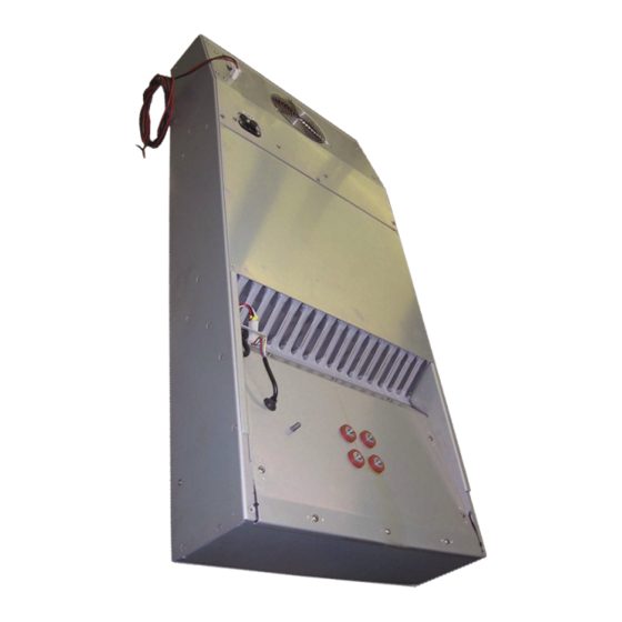
4. Technical functions Air-air heat exchangers are intended as complementary accessories to large industrial equipment which include a motor-operated fan or blower together with a heat exchanger module. These may also include an electric heater. The fan or blower is intended to recirculate air and allow heat exchange. The heat exchanger is designed for air heat transfer only. -
Page 5: Technical Data
6. Technical data Order Number 5070048 Heat exchanger performance 70 W/K Temperature range -5°C - +55°C Ambient air circuit 500 m³/h Air volume flow (system / unimpeded) Cabinet air circuit 600 m³/h Mounting Internal Housing Material Aluminum Dimension H x W x D... -
Page 6: Mounting
7. Mounting Danger from electrical voltage The unit must be mounted by specialist personnel (qualified electricians). The personnel must ensure that the cabinet is disconnected from the electrical supply for the duration of the mounting operation. Therefore take the cabinet out of operation, following the relevant instructions before mounting work commences. Danger through incorrect work on the unit. -
Page 7: Electrical Connection
8. Electrical connection High electric voltage present. Installation, maintenance, cleaning and any other work must be carried out by qualified personnel only. The personnel must ensure that for the duration of this work the unit and the cabinet are disconnected from the electrical supply and protected against unauthorised/accidental reconnection. -
Page 8: Wiring Diagram
9. Wiring diagram ALARM LEDs LED 1 OK (green) LED 2 Internal fan alarm (red) AFF LED 3 Ambient fan alarm (red) HTF LED 4 High temperature alarm (red) LED 5 Heater alarm (red) LED 2, 3, 4 and 5 Thermistor alarm (red) Alarms interface connector D-Type connector AMP 9 –... - Page 9 Version Nr. 1-1 - 18.03.2020 Doc. Nr. 995070048 9 / 11...
-
Page 10: Taking Into Operation
10. Taking into operation As described before the unit is controlled in relation to the cabinet internal temperature. The required cabinet temperature can be set on the potentiometer on the controller.The temperature adjustment range is between 0°C (left-hand stop) and 60°C (right-hand stop). The thermostat is pre-set at 35°C. To adjust the cabinet internal temperature proceed as follows: Remove the MCB access plate on the front of the unit. -
Page 11: Transport & Storage
1 x Power cable 1 x Brass connection ¼” with washer Seifert Systems GmbH Seifert Systems Ltd. Seifert Systems AG Seifert Systems Inc. Seifert Systems Pty Ltd. Albert - Einstein Str. 3 HF09/10 Wilerstrasse 16 75 Circuit Drive 105 Lewis Road...
Need help?
Do you have a question about the 5070048 and is the answer not in the manual?
Questions and answers