Table of Contents
Advertisement
Available languages
Available languages
Quick Links
Advertisement
Table of Contents

Related Manuals for Steren WR-804UHF


Summary of Contents for Steren WR-804UHF
- Page 2 Micrófonos inalámbricos UHF de solapa o diadema. Por favor, revíselo completamente para estar seguro de cómo utilizar apropiadamente el producto. Para apoyo, compras y todo lo nuevo que tiene Steren, visite nuestro sitio web: www.steren.com La información que se muestra en este manual sirve únicamente como referencia sobre el producto.
- Page 3 IMPORTANTE • No use ni almacene este equipo en lugares donde existan goteras o salpicaduras de agua. • No golpee ni deje caer los micrófonos. • Siempre utilice un paño suave, limpio y seco para limpiar el equipo. • No use los micrófonos en condiciones de polvo o humedad, calor excesivo, cerca de fuentes de calor o vibraciones mecánicas.
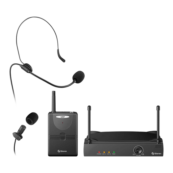
- Page 4 CONTENIDO 1. Micrófono de diadema UHF 2. Micrófono de solapa UHF 3. Transmisor UHF 4. Receptor UHF 5. Convertidor CA/CC 6. Cable de audio. RECEIVER TRANSMITTER POWER ANTENNA AUDIO VOLUME PEAK...
-
Page 5: Panel Frontal
CONTROLES Panel frontal 1. LED indicador de encendido. 2. LEDs indicadores de recepción por canal. 3. LED indicador de pico de audio. 4. Control de volumen 5. Antena receptora. RECEIVER TRANSMITTER POWER ANTENNA AUDIO VOLUME PEAK... -
Page 6: Panel Trasero
Panel trasero 6. Salida de audio desbalanceada 6,3 mm. 7. Salida de audio balanceada Cannon. 8. Control “Squelch”: Permite ajustar la calidad de la señal eliminando el ruido. 9. Entrada del adaptador de corriente eléctrica. DC INPUT UNBALANCED 12-18 VDC HIGH Z SQUELCH BALANCED... - Page 7 2. Conecte un micrófono (solapa o diadema) al transmisor y asegúrelo girando el conector. 3. Conecte el adaptador de corriente al receptor (entrada DC INPUT) y luego a un tomacorriente. DC INPUT UNBALANCED 12-18 VDC HIGH Z SQUELCH BALANCED LOW Z 4.
- Page 8 5. Extienda las antenas del receptor y colóquelas en una posición en la que reciban la señal de los micrófonos de forma adecuada. RECEIVER TRANSMITTER POWER ANTENNA AUDIO VOLUME PEAK 6. Encienda el transmisor. 7. Ajuste el volumen del micrófono en el receptor.
-
Page 9: Problemas Y Soluciones
8. Ajuste el nivel de ganancia en el transmisor; incremente o disminuya el nivel de ganancia hasta que la señal de audio sea sufi cientemente fuerte y no se distorsione. 9. Comience a usar el micrófono, hable o cante, no golpee ni sople en ellos. El LED indicador se encenderá... -
Page 10: Especificaciones
ESPECIFICACIONES Micrófono Alimentación (micrófono de diadema/solapa): 9 V- - - (batería cuadrada) Rango en frecuencia: 800 MHz – 822 MHz Estabilidad: 50 PPM (-10° ~ 50 °C) Poder de transmisión: 10 dBm Máximo nivel de entrada: 0 dBV Temperatura de operación: -10 °C ~ 50 °C Receptor Alimentación:... - Page 11 1.- Para hacer efectiva la garantía, presente esta póliza y el producto, en donde fue adquirido o en Electrónica Steren S.A. de C.V. 2.- Electrónica Steren S.A de C.V. se compromete a reparar el producto en caso de estar defectuoso sin ningún cargo al consumidor. Los gastos de transportación serán cubiertos por el proveedor.
- Page 13 Steren, visit our website: www.steren.com The instructions of this manual are for reference about the product. There may be differences due to updates. Please check our web site (www.steren.com) to obtain the latest version of the instruction manual.
- Page 14 IMPORTANT • Do not use or store the equipment near wet places. • Do not bump or drop the microphones. • Clean only with a soft, dry cloth. • Do not use the microphone if it is exposed to direct sunlight, extreme heat, dust or moisture.
- Page 15 CONTENT 1. Headset UHF microphone 2. Tie UHF microphone 3. UHF transmitter 4. UHF receiver 5. AC/DC power converter 6. Audio cable RECEIVER TRANSMITTER POWER ANTENNA AUDIO VOLUME PEAK...
-
Page 16: Front Panel
CONTROLS Front panel 1. Power indicator LED. 2. Per channel reception LEDs. 3. Audio peak indicator LED. 4. Volume control 5. Receiving antenna. RECEIVER TRANSMITTER POWER ANTENNA AUDIO VOLUME PEAK... -
Page 17: Rear Panel
Rear panel 6. Audio out unbalanced 6.3 mm. 7. Cannon balanced audio output. 8. “Squelch” control: Adjusts the signal quality by removing noise. 9. Power adapter input. DC INPUT UNBALANCED 12-18 VDC HIGH Z SQUELCH BALANCED LOW Z OPERATION 1. Open the transmitter battery compartment and insert a 9 V square battery. - Page 18 2. Connect a microphone (lapel or headset) to the transmitter and secure it by turning the connector. 3. Connect the power adapter to the receiver (DC INPUT) and then into an electrical outlet. DC INPUT UNBALANCED 12-18 VDC HIGH Z SQUELCH BALANCED LOW Z...
- Page 19 5. Extend the antenna of the receiver and into a position in which to receive the signal of the microphones properly. RECEIVER TRANSMITTER POWER ANTENNA AUDIO VOLUME PEAK 6. Turn on the transmitter. 7. Adjust the volume of the microphone in the receiver.
-
Page 20: Troubleshooting
8. Adjust the gain on the transmitter; increase or decrease gain control until the audio signal is suffi ciently strong and not distorted. 9. Start using the microphone, talk or sing, do not hit or blow on them. The LED indicator will light when the transmitter’s battery is low. -
Page 21: Specifications
SPECIFICATIONS Microphone Input (tie / headset microphone): 9 V- - - (square battery) Frequency range: 800 MHz – 822 MHz Stability: 50 PPM (-10° ~ 50 °C) Transmission power: 10 dBm Maximum input level: 0 dBV Operational temperature: -10 °C ~ 50 °C Receiver Input: 13.5 V- - - 800 mA... - Page 22 Part number: WR-804UHF Brand: Steren WARRANTY This Steren product is warranted under normal usage against defects in workmanship and materials to the original purchaser for one year from the date of purchase. CONDITIONS 1. This warranty card with all the required information, invoice, product box or package, and product, must be presented when warranty service is required.
Need help?
Do you have a question about the WR-804UHF and is the answer not in the manual?
Questions and answers