Advertisement
Quick Links
Advertisement

Related Manuals for Magna BluePirat Remote


Summary of Contents for Magna BluePirat Remote
- Page 1 BLUEPIRAT Remote / Remote Control Touch User Manual / 01.01.2020 Version 3.4.3...
- Page 2 4.1 Further manuals ....................9 4.2 Additional features by optional licenses ............10 4.3 Firmware Care ....................11 5 Remote Control Touch / BLUEPIRAT Remote – hardware .... 12 5.1 Position of connectors and operating elements ..........12 5.1.1 Top view ....................... 12 5.1.2 Side view, from the right ..................
- Page 3 REMOTE CONTROL TOUCH | USER MANUAL/ page 3 of 83 6.2.2.2 Driver View – Marker list ................36 6.2.2.3 Driver View – Notifications ................37 6.2.2.4 Driver View – Test drive ................38 6.2.2.5 Driver View – Shutdown ................39 6.2.3 The application [Busload] | ................
- Page 4 8.1 Regulatory Information only for the Remote Control Touch ......71 9 Data sheet Remote Control Touch ..........72 10 Data sheet BLUEPIRAT Remote ............72 11 Pin assignments and harnesses ............. 75 11.1 Pinout of Remote Control Touch connector ............ 75 11.1.1...
- Page 5 Licensor is and remains the owner of all titles, rights and interests in the soft- ware. The software is a copyright property of the MAGNA Telemotive GmbH. The program or parts of it may not be further licensed to third parts, rented, sold or be further marketed in any form without explicit written ap- proval by MAGNA Telemotive GmbH.
- Page 6 REMOTE CONTROL TOUCH | USER MANUAL/ page 6 of 83 PRODUCT LIABILITY The General Terms and Conditions of Sale and Delivery of MAGNA Telemotive GmbH can be found on our website (www.telemotive.de) under imprint.
- Page 7 BLUEPIRAT Remote of MAGNA Telemotive GmbH. This user guide describes the configuration and usage of this feature. The general configuration is described in the user guides of the used data logger as well as the System Client, which is valid for all devices.
- Page 8 One remote control can handle all connected loggers. BLUEPIRAT Remote While Remote Control Touch is just a control unit for handling unique devices or a TSL network, the BLUEPIRAT Remote additional has logger functionality by offering internal storage and some interfaces. License For some additional features an installed license is required.
- Page 9 User manual for Remote Control Touch https://sc.telemotive.de/4/uploads/media/RCTouch_UserGuide.pdf User manual for BLUEPIRAT Remote https://sc.telemotive.de/4/uploads/media/blue_PiraT_Remote_UserGuide.pdf For having an easy access if necessary, the most important manuals are linked in the client un- der the menu item [Help] and are reachable easily from there.
- Page 10 REMOTE CONTROL TOUCH | USER MANUAL/ page 10 of 83 Additional features by optional licenses Additional features can be activated by purchasing and installing licenses. Licenses can be or- dered at our sales team. You find the user guides for these additional features in the Service- Center.
- Page 11 REMOTE CONTROL TOUCH | USER MANUAL/ page 11 of 83 Firmware Care MAGNA Telemotive GmbH invests a great amount in the further development of its products. For this we regularly provide new functions and enhancements via firmware and client releases. Basic conditions As part of the "...
- Page 12 Remote Control Touch / BLUEPIRAT Remote – hard- ware This chapter describes the hardware of the Remote Control Touch and BLUEPIRAT Remote. The position and function of all interfaces, the accessories and the installation of hard- and soft- ware are explained.
- Page 13 REMOTE CONTROL TOUCH | USER MANUAL/ page 13 of 83 8-pol LEMO socket (RCT) 26 pol SUB-D (bPR) 2x Gbit Ethernet (RJ45) Figure 5.2: Side view, from the right with connectors 5.1.3 Rear side SD card slot Micro-USB 6 4-pol audio jack plug stereo out/microphone (3.5 mm) OMTP Figure 5.3: Rear side view with connectors...
- Page 14 REMOTE CONTROL TOUCH | USER MANUAL/ page 14 of 83 Functionality of connectors and operating elements The functionality of connectors and operating elements is impaired by certain conditions such as moisture, darkness, heat or cold, mechanical action, dirt or similar. Observe therefore the points described in chapter 8 Maintenance provisions, safety regulations.
- Page 15 5.2.4 Speaker The speaker is used to play voice notes. Its volume is adjustable. 5.2.5 LEDs Activity and operating state of the Remote Control Touch and BLUEPIRAT Remote are indi- cated by the LEDs. Activity Behavior / operating state Active LED...
- Page 16 The data on the USB memory can then be unreadable when it is removed during a write operation. If you turn off the BLUEPIRAT Remote with the [ON / Trigger] button, you have 5 seconds to remove the medium before the logger can be reawakened.
- Page 17 5.2.9 SD card slot (BLUEPIRAT Remote only) The BLUEPIRAT Remote offers the possibility to store data parallel to a removable media as SD card or USB device. The configuration of this feature is described in the System Client user guide.
- Page 18 REMOTE CONTROL TOUCH | USER MANUAL/ page 18 of 83 If you turn off the BLUEPIRAT Remote with the [ON / Trigger] button, you have 5 seconds to remove the disk before the logger can be reawakened. Please find more hints for using the SD card in the manual of the System Client.
- Page 19 The Remote Control Touch is supplied with a power cable with LEMO connector to banana plug (length: ~ 1,5 m). The BLUEPIRAT Remote is connected by a 26-pol SUB-D connector to the device and has the cables for the available interfaces integrated in the cable set.
- Page 20 A cable set with 26-pol SUB-D connector to banana plug is required for the connection of the BLUEPIRAT Remote to the power supply. Figure 5.5: Power cable with 26-pol SUB-D connector to banana plug Plug the 26-pol SUB-D connector into the BLUEPIRAT Remote and the banana plug into the power supply (red/Vbat /+/Clamp 30...
- Page 21 5.4.1.3 In the network The Remote Control Touch / BLUEPIRAT Remote has two Ethernet ports. The loggers to be controlled are connected directly via Ethernet. These loggers must establish a TSL network with the Remote Control Touch / BLUEPIRAT Remote in order to be recognized. The client com- puter can be connected to a free Ethernet port of the TSL chain.
- Page 22 BLUEPIRAT Remote is configured as Automatic DHCP configuration for TSL with IP 192.168.0.233. Open your internet browser. Enter the IP address of the Remote Control Touch / BLUEPIRAT Remote in the address bar. (IP factory setting: 192.168.0.233) Press the [Enter] key.
- Page 23 REMOTE CONTROL TOUCH | USER MANUAL/ page 23 of 83 Internet Click [Save], to locally save the file on your system. Explorer Click [Accomplish]. Mozilla Click [Save file], to locally save the file on your system. Firefox Click the arrow on the right top of the browser menu and se- lect the downloaded application in the appearing context menu.
- Page 24 You can find the manual in the Client under the menu item [Help]. In our example we configured the Remote Control Touch / BLUEPIRAT Remote as DHCP- Client and connected it with the data logger (see chapter 5.4.1.2). In the next picture you can see the two devices in the client.
- Page 25 REMOTE CONTROL TOUCH | USER MANUAL/ page 25 of 83 5.6.2 Activating System Link (TSL) In the delivery status and as default values TSL is just activatet! But for sure you can modify these settings at these devices by yourself: You can activate it by clicking [TSL active] like you can see in the following picture.
- Page 26 A warning popup is shown. Tipp on [Accept]. The warning popup disappears. The Remote Control Touch / BLUEPIRAT Remote is ready when: The view [Driver view] is shown on the display and Active-LED is lightning green.
- Page 27 REMOTE CONTROL TOUCH | USER MANUAL/ page 27 of 83 Wake up the Remote Control Touch over Kl 15 In order to start the Remote Control Touch in a TSL network with the other devices, it can be waked up via KL 15. We recommend the following configuration: ...
- Page 28 REMOTE CONTROL TOUCH | USER MANUAL/ page 28 of 83 Figure 5.15: Resetting DigitalOut #2 to 0 Since Analog #1 only measures the internal voltage, the event occurs as soon as the logger starts up and the voltage rises above 10 V (Al1 > 10). The triggers are only processed after a certain boot time of the logger, so that the signal at KL 15 is enough to wake up the Remote Control Touch before it is set to 0 again via the trigger, so that the devices are not kept perma- nently awake.
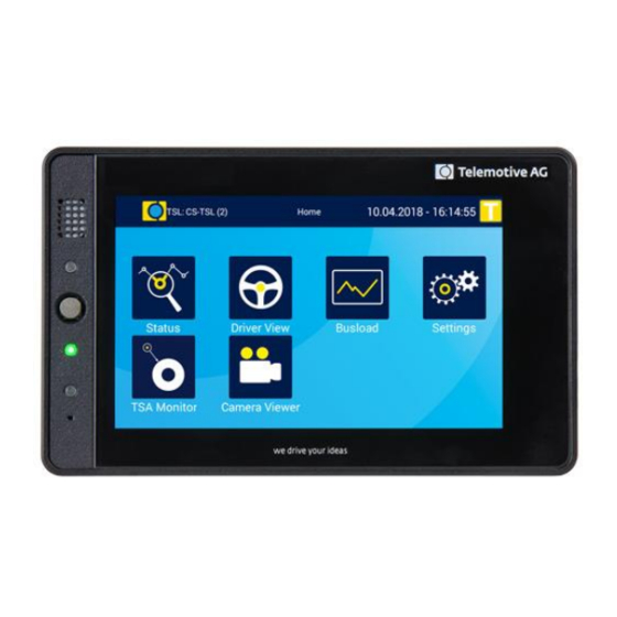
- Page 29 This chapter describes the application setup and the layout of the individual views as well as the windows inside. The Remote Control Touch / BLUEPIRAT Remote software is very user-friendly thanks to its graphic surface and the clear outline. The next figure shows the outline of the application in <Home> view and four applications. The application views contain minimum one tab.
- Page 30 REMOTE CONTROL TOUCH | USER MANUAL/ page 30 of 83 Layout of the views All views consist of a window and a dark blue frame. As the window contents vary depending on the view, they are described in more detail in the fol- lowing sections of this chapter.
- Page 31 REMOTE CONTROL TOUCH | USER MANUAL/ page 31 of 83 In the application views, the header bar contains on the left: the button respectively for the side menu, the icon of the current application (see section 6.2) and ...
- Page 32 REMOTE CONTROL TOUCH | USER MANUAL/ page 32 of 83 6.1.2 Side menu Over the button on the left of the header bar you can access the other applications. Figure 6.3: Unfolded page menu The side menu is closed by the following actions: ...
- Page 33 REMOTE CONTROL TOUCH | USER MANUAL/ page 33 of 83 Applications | An icon has been set for each of the applications to start them more easily. In the [Home] view and the side menu these icons serve as shortcuts to the applications and on the tab sheets they serve for orientation.
- Page 34 REMOTE CONTROL TOUCH | USER MANUAL/ page 34 of 83 6.2.1 The application [Status] | Display of information on the connected devices The application Status contains minimum two tab sheets: the tab sheet [Overview] and the tab sheet of the Remote Control Touch / BLUEPI- RAT Remote with the name assigned in the System Client.
- Page 35 REMOTE CONTROL TOUCH | USER MANUAL/ page 35 of 83 DHCP mode Terminal IP address and subnet mask Storage capacity Memory percentage filled Memory percentage protected Device status Error count The window of these tab sheets, with the exception of the Remote Control Touch window, con- tains the following displays: Figure 6.6: Tab sheet “*Device name n*”...
- Page 36 REMOTE CONTROL TOUCH | USER MANUAL/ page 36 of 83 6.2.2 The application [Driver View] | Management of the function keys, markers and voice notes The application Driver View is used for setting triggers, recording voice notes or pressing the function keys. Further functions are overviews of existing markers and hints, administration of test drives and shutdown the TSL network.
- Page 37 REMOTE CONTROL TOUCH | USER MANUAL/ page 37 of 83 Driver View – Notifications 6.2.2.3 The tab [Notifications] shows on the left side again the Trigger- and Recod-button and on the right side some notifications. These can be as well actions which are intialised by the client as warnings and errors of the devices.
- Page 38 REMOTE CONTROL TOUCH | USER MANUAL/ page 38 of 83 Driver View – Test drive 6.2.2.4 On the tab [Test drive] you can start test drives which can be analysed separately by the Sys- tem Client. [Trigger] button Test drive list [Start / Stop] button Figure 6.15: Tab sheet “Test drive”...
- Page 39 REMOTE CONTROL TOUCH | USER MANUAL/ page 39 of 83 When the test drive is running, the recording can be stopped by the button [Stop test drive]. The test drive is even active, when the TSL cluster goes into standby in the meantime. During a test drive, the title bar is orange and indicates permanently that a test drive is active.
- Page 40 REMOTE CONTROL TOUCH | USER MANUAL/ page 40 of 83 6.2.3 The application [Busload] | Display of all available buses and their channels The application Busload contains one combined tab sheet for each avail- able interface of the connected loggers. The tab sheets are named after the respective bus interface.
- Page 41 REMOTE CONTROL TOUCH | USER MANUAL/ page 41 of 83 6.2.3.2 Busload - MOST150 Each connected logger that receives MOST150 messages generates its own tab sheet [MOST150] with the following displays: Logger name Message Bus load Messages category per second Figure 6.21: Tab sheet “MOST150”...
- Page 42 REMOTE CONTROL TOUCH | USER MANUAL/ page 42 of 83 Category Meaning Control Control data; for the passing of control messages; transmits up to 384 data byte MOST Data Packet; transmits up to 1524 data byte MOST Ethernet Packet; for the passing of Ethernet messages; transmits up to 1506 data byte Streaming Chan- Synchronous data range;...
- Page 43 REMOTE CONTROL TOUCH | USER MANUAL/ page 43 of 83 No satellite or too few satellites were found (minimum 3). Figure 6.25: Tab sheet “GPS”: No GPS signal 6.2.4 The application [Settings] | Adjustment of backlight and volume The application Settings can be used for adjusting the brightness of the display as well as the volume of the audio playback.
- Page 44 REMOTE CONTROL TOUCH | USER MANUAL/ page 44 of 83 3. Volume scale with volume slider 4. and 5. Intern/Extern button To adjust a button, tap on the button or in the gray boundary. To adjust a slider, swipe it to or tap on the desired position on the brightness scale. More information on the operation is provided in chapter 7.
- Page 45 REMOTE CONTROL TOUCH | USER MANUAL/ page 45 of 83 Settings – Orientation 6.2.4.2 Sometimes it makes sense during installation to mount the cables in a certain direction. In order to install the device more flexibly in this case, the display can be rotated by 180 °. Figure 6.27: The view [Settings] =>...
- Page 46 The application [TSA Monitor] | Display of TSA modules Since release 3.4.1 the RCTouch | BLUEPIRAT Remote offers the ability to show installed TSA Modules with the application TSA Monitor. You’ll find more information about TSA in the manual of the System Cli- ent.
- Page 47 REMOTE CONTROL TOUCH | USER MANUAL/ page 47 of 83 6.2.6 The application [Camera Viewer] | Live view of an connected camera The application Camera Viewer shows a liveview from all available cameras in the TSL cluster. From firmware release 3.2.1, the live images of connected cameras can be shown on the dis- play too.
- Page 48 REMOTE CONTROL TOUCH | USER MANUAL/ page 48 of 83 If you tip on one of the cameras in the list, the pictures of this camera are displayed. The exam- ple shows 4 pictures from different cameras which are connected to an Axis F44. F1005-E | 113°...
- Page 49 49 of 83 Display The display of the Remote Control Touch / BLUEPIRAT Remote is similar to those of the data loggers. An overview to their meanings is provided in the following table. You can find the view that contains the display via the cross reference in the column “See”.
- Page 50 REMOTE CONTROL TOUCH | USER MANUAL/ page 50 of 83 Memory percentage indicates the percentage of the memory Fehler! Verweisquelle konnte n filled capacity that is filled icht gefunden werden. Table 6.4: Displays overview 6.3.1 Device status The device status may display the following messages: Message Form Meaning...
- Page 51 REMOTE CONTROL TOUCH | USER MANUAL/ page 51 of 83 When you tap the bottom tab bar on the logger with the "Memory" status, the detailed view of the logger opens. In this view the two flashing cells [100% filled] and [Memory], serve as an indi- cation for the full memory.
- Page 52 Timing Internal communication has failed. Options close popup To close the popup, tap on [OK]. Then repeat the last command. 6.4.2 FW-Update Precondition none Timing Remote Control Touch / BLUEPIRAT Remote firmware is updated. Options none Figure 6.35: FW-Update view...
- Page 53 REMOTE CONTROL TOUCH | USER MANUAL/ page 53 of 83 6.4.3 Launcher Precondition none Timing Remote Control Touch / BLUEPIRAT Remote is switched on. (before the application) Options close popup Figure 6.36: Launcher view “Launcher” a Within the view safety message...
- Page 54 REMOTE CONTROL TOUCH | USER MANUAL/ page 54 of 83 Figure 6.38: Window “RC Monitor”...
- Page 55 To exit the standby mode, press the Home button or tap on the screen. Restrictions of the RC Touch in stand-alone mode The BLUEPIRAT Remote can be configured by the System Client like every other data logger of Telemotive. For Remote Control Touch the following restrictions are valid:...
- Page 56 REMOTE CONTROL TOUCH | USER MANUAL/ page 56 of 83 6.5.1 Remote Control Touch applications In standalone mode the Remote Control Touch is not connected to any data logger. Some functions are therefore not available. The application Status remains unaffected. ...
- Page 57 REMOTE CONTROL TOUCH | USER MANUAL/ page 57 of 83 Open configuration Update firmware Open bug report Figure 6.42: Tab “Network Logger” in standalone mode The applications [Update firmware] and [Open bug report] provide the same functional range in both modes. Find the applications descriptions in the User manual for the System Client.
- Page 58 REMOTE CONTROL TOUCH | USER MANUAL/ page 58 of 83 Figure 6.43: Configuration trees: Standalone mode (left) – TSL (right) Find more information about components of the configuration tree in the User manual for the System Client.
- Page 59 59 of 83 Operation Important: Only use the tip of the finger to operate the Remote Control Touch / BLUEPIRAT Remote. This chapter describes instructions that are possible using the devices. Switching the device on Press the Home button.
- Page 60 REMOTE CONTROL TOUCH | USER MANUAL/ page 60 of 83 8. Press the Home button … Active LED lights up briefly. <Home> view appears. 9. Open the side menu (see section 7.9) … and tap on the icon of the desired application. Actuating functionkey Navigate to the tab sheet [Functionkeys] in the application Driver View Tap on the desired functionkey that was previously assigned with a “complex trigger”, see sec-...
- Page 61 REMOTE CONTROL TOUCH | USER MANUAL/ page 61 of 83 A tone is produced to simulate the newly set volume. If you set the volume to “Volume: 0%”, the Remote Control Touch is mute. Its acoustic signals are switched off. Navigate to the tab sheet [General] in the application Settings Swipe the volume slider to the desired position or tap on the desired position on the volume scale.
- Page 62 REMOTE CONTROL TOUCH | USER MANUAL/ page 62 of 83 Figure 7.4: Busload view with global trigger button You can set a marker by tapping the yellow trigger button. After you have set a marker, you can see a small grey popup including the marker number, the date and the time of the marker. Figure 7.5: Marker popup in the Busload view...
- Page 63 REMOTE CONTROL TOUCH | USER MANUAL/ page 63 of 83 7.10.1 Marker with voice note Navigate to one of the tab sheets [Function keys] / [Marker list] / [Notifications] in the appli- cation Driver View Note: The quality of the recording and playback is dependent on the settings of <Speaker> and <Microphone>...
- Page 64 REMOTE CONTROL TOUCH | USER MANUAL/ page 64 of 83 To stop the recording, tap on [Record] again or wait until the <Max. recording length> configured in the System Client elapses. Two brief fade-ins appear one after the other: ...
- Page 65 REMOTE CONTROL TOUCH | USER MANUAL/ page 65 of 83 7.11 Playing voice note Note: If you do not hear an acoustic signal, increase the volume (see section 7.7). The quality of the recording and playback is dependent on the <Speaker> and <Micro- phone>...
- Page 66 Dialog opens. Select the desired firmware, click on [Open]. Note: For the Remote Control Touch as well as BLUEPIRAT Remote you need the same firm- ware as for the BLUEPIRAT Mini. Figure 7.12: Opening firmware-packet Selected firmware appears in the display field.
- Page 67 REMOTE CONTROL TOUCH | USER MANUAL/ page 67 of 83 Figure 7.13: Valid firmware-packet Note: If you select an invalid firmware-packet, the following notice message appears and the [Update firmware…] button remains inactive. Figure 7.14: Notice message for invalid firmware-packet Click on [Update firmware…].
- Page 68 REMOTE CONTROL TOUCH | USER MANUAL/ page 68 of 83 Figure 7.16: Advancing firmware update The firmware is updated when: the view “FW-Update” disappears, the State LED goes out and the [Close] button is active.
- Page 69 REMOTE CONTROL TOUCH | USER MANUAL/ page 69 of 83 Maintenance provisions, safety regulations and Regu- latory Information Note according to standard EN55011:2009 The device is used in an industrial environment. Due to occurring, grid-bound as well as radi- ated disturbances, it might possibly be difficult to ensure compliance with electromagnetic com- patibility in other environments.
- Page 70 While operating the device in an automobile, the connected antennas must not be located out- side of the vehicle. Replacing the battery A lithium button cell is located within the device, which must be only replaced by MAGNA Telemotive GmbH. Mechanical exposure...
- Page 71 REMOTE CONTROL TOUCH | USER MANUAL/ page 71 of 83 Proper operation The remote control touch must exclusively be utilized with the application of MAGNA Telemotive GmbH. The application is solely compatible with System Client Wiring with third-party units is conducted at your own risk ...
- Page 72 Luminance 700 cd/m² Touch function Resistive, multi-touch Table 9.1: Data sheet Remote Control Touch Index Data sheet BLUEPIRAT Remote General data Nominal power supply voltage 13.8 V Power supply voltage 7 V to 28 V for system startup 5 V to 29 V operating voltage...
- Page 73 REMOTE CONTROL TOUCH | USER MANUAL/ page 73 of 83 Weight (ca.) 415 g Power Management Startup time < 35 s from standby to full operation Start of logging - CAN, LIN, Serial, Analog, Digital starting from standby < 200 ms Standby Mode Configurable time without bus load Wake...
- Page 74 Sampling interval 1 ms to 100 s Digital input Channel 1x Ubat (internal), 2x external (physically identical with analog input) Switching threshold 7 V ± 0.2 V Sampling interval 1 ms to 100 s Table 10.1: Data sheet BLUEPIRAT Remote...
- Page 75 REMOTE CONTROL TOUCH | USER MANUAL/ page 75 of 83 Pin assignments and harnesses 11.1 Pinout of Remote Control Touch connector As against to the Remote Control Voice, where the whole communication was send over this cable, the Remote Control Touch only uses this cable for power. Lumberg KV81-8 Pin Lemo Pin Bananaplug Pin...
- Page 76 KFZ V24 RX 0 Serial RS232 #1 RX DSUB-9 / male KFZ V24 TX 0 Serial RS232 #1 TX DSUB-9 / male LIN 0 LIN 1 DSUB-9 / male Table 11.2: Contacts of the 26-pol SUB-D plug of BLUEPIRAT Remote...
- Page 77 BLUEPIRAT Processing Information Recording Analyzing Tool BLUEPIRAT BLUEPIRAT2 bP2 5E BLUEPIRAT2 5E bPMini BLUEPIRAT Mini Remote Control Touch BLUEPIRAT Remote ASAM MCD-2 MC Language Automotive Electronics ACKnowledged Controller Area Network CAN Calibration Protocol Compact Flash Command Receive Object Data Acquisition...
- Page 78 REMOTE CONTROL TOUCH | USER MANUAL/ page 78 of 83 Electronic Control Unit FIBEX FIeld Bus Exchange Format Firmware Greenwich Mean Time INCA INtegrated Calibration and Application Tool Local Area Network = Netzwerk Local Interconnect Network Media Access Control Measure Calibrate Diagnose Meta Data EXchange Format MOST Ethernet Packet MOST...
- Page 79 REMOTE CONTROL TOUCH | USER MANUAL/ page 79 of 83 List of figures Figure 4.1: links to the manuals ....................9 Figure 5.1: Top view with operating elements ................12 Figure 5.2: Side view, from the right with connectors ..............13 Figure 5.3: Rear side view with connectors ................
- Page 80 REMOTE CONTROL TOUCH | USER MANUAL/ page 80 of 83 Figure 6.39: Window “RC Text” ....................55 Figure 6.40: Standby view ......................55 Figure 6.41: Available applications for a data logger ..............56 Figure 6.42: Tab “Network Logger” in standalone mode ............57 Figure 6.43: Configuration trees: Standalone mode (left) –...
- Page 81 Table 10.1: Data sheet BLUEPIRAT Remote ................74 Table 11.1: Contacts of the angeled Lemo plug ............... 75 Table 11.2: Contacts of the 26-pol SUB-D plug of BLUEPIRAT Remote ........76 Table 12.1: Abbreviations ......................78 Table 15.1: Version history ....................... 82...
- Page 82 REMOTE CONTROL TOUCH | USER MANUAL/ page 82 of 83 Version history Version Änderung Datum Table 15.1: Version history...
- Page 83 TMO.info@magna.com Web: www.telemotive.de Sales Tel.: +49 89 357186-550 Fax.: +49 89 357186-520 E-Mail: TMO.Sales@magna.com Support Tel.: +49 89 357186-518 E-Mail: TMO.productsupport@magna.com ServiceCenter: https://sc.telemotive.de/bluepirat © by MAGNA Telemotive GmbH Subject to errors and to technical changes as part of product improvement.
Need help?
Do you have a question about the BluePirat Remote and is the answer not in the manual?
Questions and answers