Mitsubishi Heavy Industries Superlink SC-WBGW256 Original Instructions Manual
Web & bacnet gateway
Hide thumbs
Also See for Superlink SC-WBGW256:
- Installation manual (2 pages) ,
- Configuration manual (24 pages)
Table of Contents
Advertisement
Advertisement
Table of Contents

Related Manuals for Mitsubishi Heavy Industries Superlink SC-WBGW256


Summary of Contents for Mitsubishi Heavy Industries Superlink SC-WBGW256
- Page 2 Thank you for purchasing the Gateway SC- WBGW256. Before using the product, read this manual thoroughly to ensure you learn how to operate it correctly. After reading this manual, store it in a safe location for future reference. It will be helpful to reference this manual should you have any questions or problems.
-
Page 3: Table Of Contents
Table of contents ■Before you use .............................. 3 ■Safety precautions ..........................3 ■Introduction ..............................5 ■System outline ............................5 ■Personal computer environment ......................6 ■Connections ............................6 ■Personal computer initial configuration ....................6 ■External dimensions ..........................8 ■Menu item ............................... 9 ■Operation .............................. -
Page 4: Before You Use
■ Before you use ■ Safety precautions ● Please read the precautions written here carefully to operate the gateway properly. You are required to observe these fully because every item of these instructions is important for safety. Failure to follow these instructions may result in serious consequences such as WARNING death, severe injury, etc. - Page 5 CAUTION Do not use or let others use the gateway as play equipment. Improper operations could cause ill health or health disorders. Never disassemble the gateway. If you touch internal parts accidentally, you could get electric shocks or cause trouble. Consult your dealer when it is necessary to inspect its interior.
-
Page 6: Introduction
■ Introduction This gateway does centralized monitoring and control of air conditioners from a computer. ■ System outline The diagram below shows the system configuration. The gateway connected to air conditioners is connected to the personal computer used for monitoring and control by an Ethernet cable. A logical unit of monitoring and control is the “Air-conditioner Cell”... -
Page 7: Personal Computer Environment
■ Personal computer environment ●Please check that the computer meets the following specifications : 500MHz or higher (2GHz or higher is recommended) ・CPU : 512MB or higher (1GB or higher is recommended) ・Memory ・Screen size : 1366×768 or higher ●OS and browser The combination of the OS and Web browser of the control monitoring computer is as follows. - Page 8 ●Browser (Internet Explorer) Configuration Open Internet Explorer, then select “Internet Options” from the “Tools” menu at the top of the screen and carry out the following settings. ・In “General” Home Page http://192.168.0.110/en/ (If you changed the IP address of the gateway, you have to input that IP address instead of 192.168.0.110 in the address column.
-
Page 9: External Dimensions
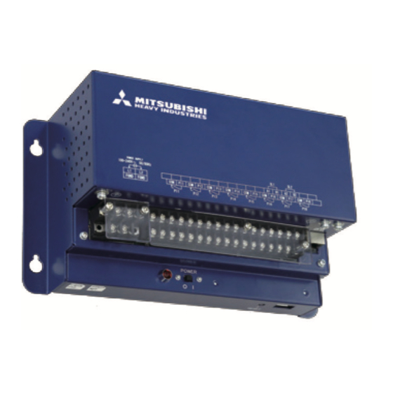
■ External dimensions Model Name Label Power switch Power indicator Reset button... -
Page 10: Menu Item
■ Menu item Overview Monitor Individual Monitor Login screen screen screen Control Command screen Schedule Control screen System Stop/Release screen Air-conditioner Cell Basic Configuration Configuration Menu Configuration Menu screen screen screen Air-conditioner Cell Configuration File Upload/Download screen Network Configuration screen Date and Time Configuration screen Security... -
Page 11: Operation
■ Operation ■ Basic operation ●Logging In The login screen is the starting screen for the gateway. The login screen is displayed by inputting the URL of the gateway from the computer’s web browser. 1. Start the computer’s browser (Internet Explorer). 2. -
Page 12: Overview Monitor Screen
●Overview Monitor screen This screen is displayed when you log in. This screen is for monitoring the overview of the whole air conditioner system. It is capable of monitoring up to 256 Air-conditioner Cells (air conditioner remote control group connection units). It displays the name of each Air-conditioner Cell, an error display icon, and the On/Off/Operation Mode icon. - Page 13 ・ When “Buzzer ON” is selected on the WEB Configuration screen, the alarm buzzer function that gives the warning by sounding the buzzer when any error has occurred in an Air-conditioner Cell, is enabled. (See page 33.) The alarm buzzer function works not only on this screen but also on any screen of this gateway. When the buzzer is sounding, the Buzzer Off button is shown at the left side of the screen on all screens.
-
Page 14: Individual Monitor Screen
●Individual Monitor screen This screen is for indicating the detailed information on one Air-conditioner Cell in a pop-up window on the Overview Monitor screen. 5. Click the name of the Air-conditioner Cell you would like to monitor on the Overview Monitor screen. -
Page 15: Control Operation
■ Control operation You can use the control operation only when you log in as "System Administrator" or "Control and Monitoring User". ●Control Command screen Use this screen to set the control commands for each Air-conditioner Cell. Note In some models of air conditioners, it is not possible to set and display "POWERFUL". If you select anything other than blank in an item in the ALL row, the settings will be applied to all registered Air-conditioner Cells. -
Page 16: System Stop/Release Screen
●System Stop/Release screen Use this screen to stop or release all the air conditioners connected to the gateway. <System Stop> 1. Click “System Stop/Release” from the menu at the top of the screen. The System Stop/Release screen will be displayed. 2. - Page 17 <System Release> 1. Click the “System Release” button during a System Stop. The stop setting for all air conditioners will be released, the Overview Monitor screen will be displayed, and the scheduled operation from that point on will be enabled. The remote control operation returns to the state before the System Stop.
-
Page 18: Schedule Control Screen
●Schedule Control screen This screen displays the Schedule Control composed of the Master Schedule and calendar for each Air-conditioner Cell, and is used to input data and edit the Schedule Control. Every day, at the change of the date, the data of the Schedule Control is shifted by one day, and one day's data is copied from the Master Schedule to the 7th day's schedule data of the Schedule Control. - Page 19 1. Click “Schedule Control” from the menu at the top of the screen. In the initial screen, the Schedule Control of the cell with the lowest cell No. is displayed. (It may take several seconds to display this screen depending on network conditions.) Schedule Control screen 2.
-
Page 20: System Administrator Setting
■ System administrator setting You must log in as a system administrator to make these settings. ●Configuration Menu screen This screen is displayed when “Configuration Menu” is clicked from the menu at the top of the screen. The following Configuration menus are available. - Basic Configuration Menu - Web Configuration Menu - BACnet Configuration Menu... -
Page 21: Basic Configuration Menu Screen
●Basic Configuration Menu screen This screen is displayed when the “Basic Configuration Menu” link is clicked on the Configuration Menu screen. The following Basic Configuration menus are available. - Air-conditioner Cell Configuration - Air-conditioner Cell Configuration File Upload/Download - Network Configuration - Date and Time Configuration - Security Configuration - Authentication Configuration... -
Page 22: Air-Conditioner Cell Configuration Screen
●Air-conditioner Cell Configuration screen This screen is used to define the air conditioners that comprise each Air conditioner Cell and to set the name for each Air conditioner Cell, such as "Conference Room A". Air-conditioner Cell Configuration screen 1. Click “Air-conditioner Cell Configuration” in the Basic Configuration Menu screen. (See page 20.) A list of air conditioners constituting each Air conditioner Cell will be displayed. - Page 23 4. Select the Accounting Type and Capacity. The Accounting Types are shown below. • MULTI1 : Calculating according to the amount of refrigerant flow. Used for KX Series. • MULTI2 : Calculating according to Thermo ON/OFF. Used for KX Series. •...
-
Page 24: Air-Conditioner Cell Configuration File Upload/Download Screen
●Air-conditioner Cell Configuration File Upload/Download screen This screen is used to download the Air-conditioner Cell Configuration information which was set on the Air-conditioner Cell Configuration screen to a computer, or upload an Air-conditioner Cell Configuration File from a computer for control and monitoring to this gateway. An Air-conditioner Cell Configuration file is a CSV file or XML file containing a list of the SL system No., SL address, Accounting Type, Capacity, Air-conditioner Cell name, Description, meter information, and Calculation interval of each air conditioner in Air-conditioner Cells indexed by the Air-conditioner Cell No. - Page 25 <To create / edit the Air-conditioner Cell Configuration File on a computer> ・ When the air conditioner which has been listed is not connected, it's possible to delete each row. Even if the corresponding line is deleted, it shows that the air conditioner is not connected. ・...
-
Page 26: Network Configuration Screen
●Network Configuration screen This screen is used to set the IP address of web browser. 1. In the Basic Configuration Menu screen, click “Network Configuration”. (See page 20.) 2. When the IP Address was changed. 2-1. Input the desired IP Address and the Subnet Mask. Caution If a wrong IP Address is input, you will not be able to access the gateway anymore. -
Page 27: Date And Time Configuration Screen
●Date and Time Configuration screen This screen is used to set the internal time clock of the gateway or match it automatically according to the NTP server on the network. The Schedule Control is executed in accordance with this clock setting, so in order to assure correct operation, it is necessary to correct the setting on this clock regularly. - Page 28 <For Automatic adjust> 4. Select the "Using NTP" check box and input the IP address of the NTP server. Note Consult with the network administrator about the IP address of the NTP server. When you enable NTP, you cannot input the current date and time setting manually in step 3. above. 5.
-
Page 29: Security Configuration Screen
●Security Configuration screen This screen is for specifying the IP address of the computer that allows the gateway to log in. Caution Be careful not to make any mistakes in setting the IP address. No addresses are set at the factory, so any computer with any IP address can access the gateway. However, if even one IP address is entered in this screen for which access is permitted, the gateway can be accessed from only the computer with that address. -
Page 30: Authentication Configuration Screen
●Authentication Configuration screen This screen is used to set and change the User ID and Password for logging in to the gateway. 1. In the Basic Configuration Menu screen, click “Authentication Configuration”. (See page 20.) 2. Input the User ID and Password of each Authentication. (See page 10.) Input the User ID using 4-16 one-byte alphanumeric characters and the Password using 6-16 one-byte alphanumeric characters. -
Page 31: Language Configuration Screen
●Language Configuration screen This screen is used to switch the display language, and to upload or download the language configuration file (“language.xml”). The language configuration file is in the XML file format. This file is a comparison list of English and the user's language. -
Page 32: Pulse Count & Di Status Check Screen
●Pulse count & DI status Check screen You can check the total number of input pulses (updated every 1 minute) of the pulse input terminals (P1 to P8) and the input state (Open / Close) of the contact signal input terminals (DI1 to DI3). 1. -
Page 33: Web Configuration Menu Screen
●Web Configuration Menu screen This screen is displayed when the “Web Configuration Menu” link is clicked on the Configuration Menu screen. The following Web Configuration menus are available. - WEB Configuration - Link Configuration - Calendar Configuration - Master Schedule Configuration - Calendar/Schedule Backup File Upload/Download - Accounting File Download - Accounting Period Time... -
Page 34: Web Configuration Screen
●WEB Configuration screen This screen is for setting the refresh interval of the monitoring screen of the web browser. 1. From the Web Configuration Menu screen, click “WEB Configuration”. (See page 32.) 2. Set the Screen Refresh Interval. Set the screen refresh interval to 10-180 seconds. (It is set at 30 seconds at the factory.) Note The maximum delay time from the time the air conditioner’s status changes until the change is reflected on the computer screen is virtually decided by this setting. -
Page 35: Link Configuration Screen
●Link Configuration screen This screen is used to set the web linkages among a number of gateways. The linkages are a function for switching and manipulating multiple gateways in the browser. Up to 4 gateways can be set including the currently logged in gateway. -
Page 36: Calendar Configuration Screen
●Calendar Configuration screen This screen is used to set the special dates for the coming 12 months. Caution The schedule within 7 days from the current day cannot be changed, even if Calendar Configuration is changed. You must change the schedule in the Schedule Control screen. (See page 17.) 1. -
Page 37: Master Schedule Configuration Screen
●Master Schedule Configuration screen The Master Schedule is the data decided by the kinds of days defined in the Calendar (10 types: Monday, Tuesday, Wednesday, Thursday, Friday, Saturday, Sunday, Holiday, Special Day 1, and Special Day 2). The actual schedule actions are executed by the Schedule Control. (See page 17.) Every day, at the change of the date, the data of the Schedule Control is shifted by one day, and one day's data is copied from the Master Schedule to the 7th day data of the Schedule Control. - Page 38 4. Click the “Set” button. Note ・ If you jump to the screen for another month without clicking the “Set” button, or if you click the “Undo” button, all the contents input in this screen will be deleted, so exercise caution. ・...
-
Page 39: Calendar/Schedule Backup File Upload/Download Screen
●Calendar/Schedule Backup File Upload/Download screen This screen is used to download or upload the backup files for the Calendar Configuration, Master Schedule Configuration and Schedule Control (called hereafter the schedule backup files). 1. From the Web Configuration Menu screen, click "Calendar/Schedule Backup File Upload/Download". -
Page 40: Accounting File Download Screen
●Accounting File Download screen This screen is used to download the accounting data files. Accounting data files are binary files special to WGW256Utility. Data of the last 12 months including this month is saved in the gateway and downloaded. Data in earlier months is deleted automatically. -
Page 41: Accounting Period Time Screen
●Accounting Period Time screen This screen is used to configure the time period to collect the accounting data. Accounting is calculated by dividing a day into two period times of in-time/out-time. (Common to all air conditioners) The time period for the “in-time” is configured on this screen. The time period other than this configuration is calculated as the “out-time”. -
Page 42: Troubleshooting
■ Troubleshooting Phenomenon Cause Way of Coping IP address was forgotten. Incorrect IP address was configured. Consult with the dealer where you purchased this product. Password was forgotten. Security setting IP address was forgotten. While the screen is being refreshed, this occurs for an If the flickering becomes instant until the new screen is pronounced, set the screen... -
Page 43: After Sales Service
■ After Sales Service Have the following information available when requesting repairs. ● Model name Installation date Problem status, as detailed as possible Address Name Telephone number Relocation ● Since expert techniques are required, always contact your dealer. In such cases, there will be a fee for relocation. Repairs after the free service warranty period.