Advertisement
Quick Links
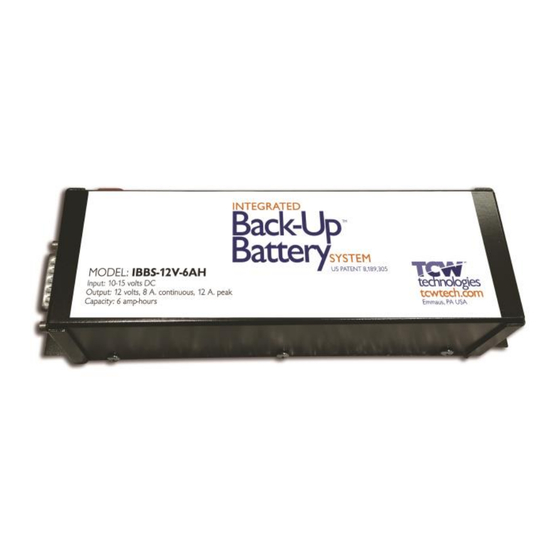
Integrated Back-up Battery System
Model: IBBS-12v-6ah
The Integrated Back-up Battery System, IBBS, is an electronic system
that combines a Lithium-Iron-Phosphate (Li-Fe-PO4) battery pack, a
charger and switching logic in one convenient package. The IBBS
provides an engineered solution to enable an endurance bus for critical
loads found in aircraft. It simplifies the wiring and installation of a source
of back-up power by integrating all of the key elements into a single
enclosure. The IBBS system provides back-up power to critical
electronic loads such as EFIS, GPS, Autopilots and engine monitor
systems.
Integral to the IBBS is a lithium-iron-phosphate battery pack and a
matched charging system to ensure the battery is properly charged and
maintained. The system also includes switching circuitry to provide a
stable source of output power during normal and emergency operations.
The IBBS system also provides signals to other equipment such as EFIS
systems to communicate the operating state of the main aircraft bus as
well as the state of the battery.
The IBBS system connects to the standard aircraft power bus and
provides an output to critical equipment that require back-up power.
Additionally, the IBBS system provides surge and sag protection for
connected equipment, allowing operation of critical equipment during
engine starting.
REV 1.6
© 2019 TCW Technologies, LLC.
1
Advertisement

Summary of Contents for TCW Technologies Integrated Back-up Battery System
- Page 1 Integrated Back-up Battery System Model: IBBS-12v-6ah The Integrated Back-up Battery System, IBBS, is an electronic system that combines a Lithium-Iron-Phosphate (Li-Fe-PO4) battery pack, a charger and switching logic in one convenient package. The IBBS provides an engineered solution to enable an endurance bus for critical loads found in aircraft.
- Page 2 13 General Wiring diagram pg. 14 Example Wiring diagrams pg. 15-19 Warranty information pg. 20 Service and Support information: 610-928-3420 TCW Technologies, LLC. www.tcwtech.com 2955 Main Road East email: support@tcwtech.com Emmaus, PA 18049 REV 1.6 © 2019 TCW Technologies, LLC.
- Page 3 (12-15). The pass-thru breaker must be sized for whatever load is connected to the IBBS outputs. The maximum combined load is 12 amps peak, 8 amps continuous. If Pins 6,7,8 are used they MUST be connected to the same power bus as Pin REV 1.6 © 2019 TCW Technologies, LLC.
- Page 4 Light Speed Electronic ignition system connects directly to aircraft battery as shown. Other brands of electronic ignition systems connect to the switch side of the aircraft master bus. Follow the instructions per the electronic ignition manufacture for your installation. REV 1.6 © 2019 TCW Technologies, LLC.
- Page 5 IBBS system completes its recharge cycle of its internal battery, for a fully discharged battery this may take up to two hours. Alternately, a ground based charger is available from TCW Technologies LLC., model # IBBS-12v-CHARGER-LI-FE.
- Page 6 The internal battery in the IBBS system is replaceable, however, the IBBS product must be returned to TCW Technologies, LLC. for this service. Battery life depends strongly on many factors including operating and storage temperature, number of discharge cycles and depth of discharge.
- Page 7 1) Operate the Aircraft Master Power Switch per the Emergency Procedure checklist already established for the aircraft. 2) Ensure the Back-up Master Switch is in the ON position. 3) Land aircraft as soon as practical to resolve the loss of main electrical power. REV 1.6 © 2019 TCW Technologies, LLC.
- Page 8 On at least an annual basis the endurance capability of the IBBS system shall be confirmed and compared against the back-up endurance required for the connected equipment. As an alternate to these tests, the IBBS unit may be returned to TCW Technologies for a loaded endurance test, contact TCW Technologies LLC. for details.
- Page 9 On at least an annual basis the endurance capability of the IBBS system shall be confirmed and compared against the back-up endurance required for the connected equipment. As an alternate to these tests the IBBS unit may be returned to TCW Technologies for a loaded endurance test, contact TCW for details.
- Page 10 This may done by operating the aircraft in conditions known to not require back-up power or by powering the aircraft system on a suitable ground power source as described in the section: Ground Base Recharging. REV 1.6 © 2019 TCW Technologies, LLC.
- Page 11 Standard density 15 pin male D-sub on product *Minimum input voltage for battery recharging. **Transition voltage is the voltage level on the input that causes the system to provide output power via the internal back-up battery REV 1.6 © 2019 TCW Technologies, LLC.
- Page 12 Pin # Function Enable- backup switch Batt-info Low Volt Warn PWR + in, charge, sensing Pwr +, pass-thru input Pwr +, pass-thru input Pwr +, pass-thru input Ground Ground Ground Output Output Output Output REV 1.6 © 2019 TCW Technologies, LLC.
- Page 13 Product mounting footprint 7.70 4 mounting holes. 0.190 Top View 1.50 2.290 7.25 0.225 Product height 2.75” REV 1.6 © 2019 TCW Technologies, LLC.
- Page 14 Pin # Function Back-up master switch Ground Batt-info Ground Low Volt Warn Ground Output PWR + in, charge, sensing Output Pwr +, pass-thru input Output Pwr +, pass-thru input Output Pwr +, pass-thru input REV 1.6 © 2019 TCW Technologies, LLC.
- Page 15 Example wiring for systems without back-up power inputs, including Electronic Ignition systems other than LSE brand. NOTE: Use redundant ground pins 9,10,11 Use redundant power inputs 6,7,8 Battery based on load current of connected equipment REV 1.6 © 2019 TCW Technologies, LLC.
- Page 16 2) Use redundant power inputs 6,7,8 based on load current of connected equipment. 3) Use of power pins will power connected equipment even when avionics bus is OFF via pass thru mode. Use of input pins 6,7,8 is OPTIONAL. REV 1.6 © 2019 TCW Technologies, LLC.
- Page 17 G3X system NOTES: 1) Use redundant ground pins 9,10,11 2) See Garmin install manual for all wiring details and fusing requirements 3) Enable Volts2 display in Garmin Set-up Software to display IBBS battery voltage REV 1.6 © 2019 TCW Technologies, LLC.
- Page 18 2) Use redundant power inputs 6,7,8 based on load current of connected equipment. 3) No back-up master switch required when wired per this drawing for AFS 5000 series. 4) Enable Volts2 display in AFS setup screen to display IBBS battery voltage REV 1.6 © 2019 TCW Technologies, LLC.
- Page 19 Wiring diagram for use with electronic ignition such as shield tied to LSE Plasma II and III battery ground Consult ignition module wiring documents for specific wiring requirements. Battery Do Not use the Low Voltage Warning LED with this application REV 1.6 © 2019 TCW Technologies, LLC.
- Page 20 TCW Technologies, LLC. During the first 12 months from the date of purchase and subject to the conditions hereinafter set forth, TCW Technologies, LLC. (TCW) will repair or replace to the original user or consumer any portion of your new TCW product which proves defective due to defective materials or workmanship of TCW.
Need help?
Do you have a question about the Integrated Back-up Battery System and is the answer not in the manual?
Questions and answers