
Related Manuals for Eagle Eye BDS-Pro


Summary of Contents for Eagle Eye BDS-Pro
- Page 1 BDS-Pro Battery Monitoring System Installation Manual 122118 www.eepowersolutions.com | Tel: 1-877-805-3377 | Fax: 1-414-962-3660 | info@eepowersolutions.com...
-
Page 2: Table Of Contents
5.6 DC Voltage Cables ......................22 5.7 Connect DC CT Clamp ....................24 5.8 Verify Connections ......................26 5.9 Connect Cables to BDS-Pro MPU .................. 28 6. Initial Power Up ........................29 6.1 Status LEDs ........................29 6.2 Keypad Operation ......................30 7. -
Page 3: Introduction
Operation methods and safety measures described in this manual are only applicable to the defined purpose and functionality of the BDS-Pro. If the BDS-Pro is used in a way not specified in this manual, the safety of the equipment, personnel, and property cannot be assured. -
Page 4: Product Overview
BDS-Pro Installation Manual 122118 2. Product Overview The BDS-Pro is designed to monitor and analyze the state of health of up to (24) cells by measuring and recording: String: Voltage & DC Float / Discharge Current Jar/Cell: Voltage, Internal Resistance / Connection Resistance, & Temperature All BDS-Pro solutions come complete with battery management software which allows all battery systems to be monitored 24 hours a day, 365 days a year via remote computer(s). -
Page 5: Main Processing Unit (Mpu)
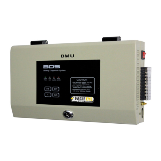
BDS-Pro Installation Manual 122118 2.1 Main Processing Unit (MPU) The MPU receives battery data and communicates with the Server. Power Button System Status Indicator Lights Terminal Strip (DC Power, DC Controls Voltage Sensing, & CT Connections) Internal Access RS232 Port (Programming &... - Page 6 BDS-Pro Installation Manual 122118...
-
Page 7: Technical Specifications
BDS-Pro Installation Manual 122118 2.2 Technical Specifications Flooded, Sealed, & NiCad battery types Applications: Up to 24 jars / cells. Battery Capacity Range: Up to 6000 Ah Cell Voltage: 1 – 16 VDC DC Voltage / Current: ±0.5% / ±1% Temperature: ±2%... -
Page 8: Parts List
BDS-Pro Installation Manual 122118 3. Parts List The following parts come standard with each BDS-Pro package. The number and type of connector clamps will depend on the application. Part Name & Purpose Picture BDS-Pro MPU Main processing unit for BDS-Pro system... - Page 9 Power cables Total Voltage Jumpers Allows total voltage measurement from DC power terminations CT Cable Harness For connection between CT & BDS-Pro MPU Temperature Cable Harness (4-pin) Measures temperature of battery posts Voltage Sensing Cable Harness (6-pin) Measures DC voltage (Vs)
-
Page 10: Installation Tools
BDS-Pro Installation Manual 122118 4. Installation Tools 4.1 Required Tools Tool Name & Purpose Picture Multi-meter Verification of connection voltage & resistance #1 Phillips Insulated Screwdriver Tightening of O-Type/C-Type clamp screws 2/16” (2-3 mm) Flathead Screwdriver Tightening of sensing cable... -
Page 11: Recommended Tools
Zip Ties Cable management Cable Duct / Panduit Cable routing Electrical Tape (Scotch Super 33+ Recommended) Cable management Cable Wrap Bind multiple cables together 4.2 Recommended Tools Tool Name & Purpose Picture IBEX Battery Tester Verification of BDS-Pro measurement readings... -
Page 12: Hardware Installation
It is recommended that experienced personnel familiar with electrical work and battery-room environments perform this installation. If a section of this guide is unclear, please contact Eagle Eye Power Solutions directly for further support. 5.1 Overview of Workflow... -
Page 13: Mpu Installation
The MPU should be mounted in the location which was determined during the Site Survey process. This location is typically indicated on the provided connection map BDS-Pro Mounted to Wall TIP: All sensing cables are factory cut to lengths based on the MPU location from the cable... -
Page 14: Clamp Installation
C-Type/O-Type Clamps Tools: Drill/Phillips Screwdriver The BDS-Pro includes clamps for installation to the inter-cell connections of the battery system. There are two clamp types: C-Clamp: Metal clamp which connects to the battery bus bars or terminal plate O-Type: Plastic clamp which connects to cables (typically between rack tiers) The purpose of the clamps to provide a non-intrusive, fused connection to the battery system for measurement. - Page 15 BDS-Pro Installation Manual 122118 (2) Connection of Clamps (C-Type) 1. Connect clamps according to the provided connection map. 2. Determine how the clamp will be placed. Generally, the cable terminations should be facing the direction the sensing cable(s) will be ran from 3.
- Page 16 BDS-Pro Installation Manual 122118 (3) Connection of Clamps (O-Type) 1. Connect clamps according to the provided connection diagram. 2. Determine how the clamp will be placed. Generally, the cable terminations should be facing the direction the sensing cable(s) will come from 3.
-
Page 17: Sensing Cable Layout & Connection
BDS-Pro Installation Manual 122118 5.4 Sensing Cable Layout & Connection Parts: Voltage Sensing Harness, Current Sensing Harness, Connection Map Tools: 2/16” (2-3mm) flathead, duct, cable ties/zip ties, wire cutter, wire stripper The sensing cables must be laid out from the MPU to each individual connection (C-Clamp or O-Clamp) on the battery system. - Page 18 BDS-Pro Installation Manual 122118 The last wire (brown) of the harness will always connect to the same (Vs) termination of the first wire (grey) of the next harness. Current Sensing Cable: Current sensing cables measure cell resistance and connect to specific clamps only (the...
- Page 19 (Ex. Laying cable ducts across front facing battery systems) Duct Installation on (8) 6V Jars NOTE: Cable ducts are included with Eagle Eye serviced installations. If performing the installation without Eagle Eye, ducts must be purchased separately. (4) Lay Sensing Cables to Each Clamp 1.
- Page 20 BDS-Pro Installation Manual 122118 5. For all clamps with multiple cables running to them, twist the cables together to minimize exposed cabling (5) Connect Sensing Leads to Clamps 1. Observe carefully which slot to is used for each sensing cable...
-
Page 21: Temperature Sensor Connection
BDS-Pro Installation Manual 122118 5.5 Temperature Sensor Connection Parts: Temperature (T) Cable Harness, Thermistor(s) Tools: Tape, Hot Glue Gun, or Silicone (1) Connect Thermistor to Temperature Sensing Cable(s) 1. The temperature sensing cable harness has a red and black wire 2. -
Page 22: Dc Voltage Cables
Tools: Phillips Screwdriver, Cable Crimper, Zip Ties The DC Voltage Cables power the BDS-Pro as well as monitor string voltage in real-time. The cables connect to the main positive and negative bus of the battery system then back to the terminal block on the BDS-Pro MPU. - Page 23 Total Voltage O-Clamp (3) Connect DC Voltage Cables to BDS-Pro MPU 1. The DC voltage cables connect to the terminal block on the BDS-Pro 2. Connect the positive and negative DC voltage cable together with the total voltage jumper cables as shown below:...
-
Page 24: Connect Dc Ct Clamp
BDS-Pro Installation Manual 122118 5.7 Connect DC CT Clamp Parts: CT Clamp, CT Cable Harness Tools: 2-3 mm flat head, zip ties The CT clamp measures float and discharge current on the battery string. Each BMS only requires (1) CT clamp. The CT provided is sourced based on the information provided during the site survey process. - Page 25 BDS-Pro Installation Manual 122118 (3) Connect CT Cable Harness to CT Clamp 1. Cut excess length from the CT cable if needed 2. Remove shielding to expose roughly 2 inches of the colored wires 3. Cut about 3 mm of shielding from each individual wire 4.
-
Page 26: Verify Connections
BDS-Pro Installation Manual 122118 5.8 Verify Connections Parts: Tools: Multimeter Before plugging cable connectors into the MPU, be sure to check each connection using an accurate multimeter to verify the voltages. The purpose of this step is to ensure that the voltage of each connection is as expected. - Page 27 BDS-Pro Installation Manual 122118 Test Connection between Clamp 1 & Clamp 5 of 12V Cells (3) Troubleshooting Incorrect Voltage 1. If voltage is incorrect, connections will need to be checked 2. Set the multi-meter to measure resistance and test the connection between the sensing screw and the sensing cable 3.
-
Page 28: Connect Cables To Bds-Pro Mpu
BDS-Pro Installation Manual 122118 5.9 Connect Cables to BDS-Pro MPU Parts: Tools: Zip/Cable Ties, Tape The voltage, current, and temperature sensing cables connect the Relay Board located inside the BDS-Pro MPU. Relay Board Connections for Sensing Cables (1) Connect all Sensing Cables to the MPU Relay Board 1. -
Page 29: Initial Power Up
WARNING: Failure to check the voltages of each sensing cable can result in permanent damage to the MPU. Ensure that all voltages are correct before powering on. To power on the BDS-Pro, flip the power switch to the on position, the LED’s on the front of the unit should illuminate. -
Page 30: Keypad Operation
NOTE: It is likely that for the initial power up the DC and BATT alarms will be blinking. The steps in Section 7 should resolve this. 6.2 Keypad Operation The BDS-Pro has a keypad for basic operation: I/O: Hold with ENT to START measurement (unit will start clicking) -
Page 31: Parameter Setup & Measurement Verification
Tools: Laptop, RJ45-USB adapter, EEPS USB drive After the hardware installation of the BDS-Pro is complete the unit should be programmed and tested on-site. During this step, the program BDS-Serial Com will be used to set parameters on the BDS as well as view measurement data to ensure the unit is operating properly. - Page 32 COM port shown (3) Configure BDS-Pro using Serial Com 1. Launch BDS-Pro Serial Com, ensure the port is correct and the baud rate is 19200 2. The program has three main areas of functionality: A. Displays string and jar measurement data and information B.
- Page 33 The DC Gain value needs to be programmed correctly based on the CT rating for the system. First check the rating on the CT clamp as shown below in red: Then enter the value in BDS-Pro Serial Com based on the chart below. DC-CT Gain Chart...
- Page 34 BDS-Pro Installation Manual 122118 NOTE: Battery parameters vary based on battery type and recommendation from the manufacture. If in doubt contact the battery manufacturer for alarm recommendations. 4. Set String Alarm Parameters Select the Command 2 tab A. Over V: Set the over string voltage value B.
- Page 35 BDS-Pro Installation Manual 122118 7. Set Jar Resistance Compensation Some jars might display a higher resistance if they are connected to a jumper (such as between racks or splits in the bank). This can be corrected using the R Compensation feature.
-
Page 36: Network Communication Setup
4. Edit only the fields listed below and outlined in red 5. Board List: The MAC address of the BDS-Pro will appear on the left column “Board List”. Record the MAC address under the MAC Address column in the IBwatch Installation... - Page 37 BDS-Pro Installation Manual 122118 6. Local IP: The Local IP field represents the IP of the BDS-Pro. Edit only the last quartet of the IP address. 7. Gateway: Enter the network/router IP in this field 8. Server IP: Enter the IP address of the Server PC in this field, this is the computer that Centroid Snet is installed on.
-
Page 38: Connect Bds-Pro To Network
BDS-Pro Installed, Ethernet Cable Tools: With the BDS-Pro installed and the IP configured, it can be connected to the company network. 1. Run the Ethernet directly into the TCP/IP port on the side of the BDS-Pro 2. Check that both lights (green & orange) are blinking...
Need help?
Do you have a question about the BDS-Pro and is the answer not in the manual?
Questions and answers