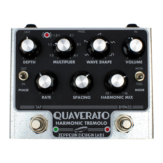
Summary of Contents for Zeppelin Design Labs QUAVERATO
- Page 1 QUAVERATO TROUBLESHOOTING GUIDE If your Quaverato kit isn’t working properly please read through this guide and follow these steps in order. You’ll be required to use your multimeter to test DC voltage, resistance, and continuity on various points.
- Page 2 Before we get started with the troubleshooting, the two most common issues that cause trouble with the Quaverato kit builds are 1) bad solder joints and 2) the jumpers not being properly soldered. There’s not much that can be done about bad solder joints until you track them down, but if the tremolo effect isn’t working at all (the pedal is just acting as a boost) chances are that you soldered the jumpers...
- Page 3 Are the lugs on the taps foot switch shorted (use your continuity tester to see if they are connected when the switch is NOT being pressed)? • If they are shorted, (neatly) re-solder the tap foot switch wires to the board. • If they are not shorted, this probably means you need a new microcontroller.
- Page 4 C. Is the relay properly switching the signal path? With the bypass LED OFF, check for continuity between the tip of the input jack and the tip of the output jack. • Check for good solder joints on the input and output jacks. • Check for good solder connections on all the relay associated components...D1, D2, Q4, Q5, R31, R32, and RL1.
- Page 5 6. Does the pedal pass audio when the bypass LED is ON and the DEPTH knob fully counter clockwise? If not... A. If not, are the jumpers soldered correctly, as in the pictures on page 48 of the assembly manual? I can’t tell you how many times people solder these wrong or not at all (...are we not communicating something clearly enough?).
- Page 6 III. Are both the HPF and LPF signal paths working? • Put the Quaverato in calibration mode (hold down both foot switches upon power up) and test to see if both the high and low frequency paths are working (by using the HARMONIC MIX knob).
- Page 7 • Are the components of this circuit soldered and installed correctly? Check R27, R28, R29, Q3, C18, C17, R33. Make sure that Q3 and C18 are not reversed, and the pads of C17 and C18 are not bridged. APENDIX A: IF ONE OF THE 2 SIDES IS NOT WORKING (EITHER HIGH OR LOW) • Make a tiny incision in the heat shrink of the optocoupler (on the side that isn’t working).
- Page 8 b. If the optocoupler’s LED is lighting up then you know the problem is with the analog part of the circuit. i. Make sure the jumpers are soldered properly ii. Check for bridged or bad solder joints on all the components on the non-working side of the circuit.
- Page 9 APENDIX C: FIXING BROKEN SOLDER JUMPER PADS Sometimes, if you apply too much heat to the solder pads they can become damaged. This usually means that one of the pads has lifted off the board and possibly lifted the trace with it. This can easily be fixed by bypassing the solder pads with a jumper wire.
- Page 10 051320...


Need help?
Do you have a question about the QUAVERATO and is the answer not in the manual?
Questions and answers