Table of Contents
Advertisement
Quick Links
Advertisement
Table of Contents

Related Manuals for Zeppelin Design Labs VPM-1


Summary of Contents for Zeppelin Design Labs VPM-1
-
Page 2: Table Of Contents
APPENDIX 3: REPLACING THE DIGITAL POTENTIOMETER ........... 25 © 2018 ZEPPELIN DESIGN LABS. NO PART OF THIS DOCUMENT MAY BE REPRODUCED WITHOUT WRITTEN PERMISSION FROM THE AUTHOR. ZEPPELIN DESIGN LABS TAKES NO RESPONSIBILITY FOR ANY DAMAGE OR HARM THAT MAY COME TO ANYONE OR ANYTHING THROUGH THEIR PRODUCTS. -
Page 3: Introduction
INTRODUCTION ABOUT THE ERNIE BALL VOLUME PEDAL The Ernie Ball volume pedal has been around since 1975. The chassis of these early volume pedals was originally made from two pieces of angle iron welded together, which earned them a reputation of being extremely robust. Later, the chassis was replaced with a solid aluminum extrusion that greatly reduced the weight while retaining the structural integrity of the original. -
Page 4: How The Vpm-1 Works
Mostly these mods just incorporate a buffer or boost circuit into the pedal to counteract the “tone suck” effects of the passive potentiometer. Here at Zeppelin Design Labs, we have been fans of the Ernie Ball VP Jr for years, and have developed our own mod. Born out of a frustration with its limitations and a passion for its potential, we have created what we think is the “mother of all volume pedal mods.”... - Page 5 “pan” pedal, where one audio channel gets louder as the other gets quieter. Pan mode enables the user to pan between two different signals. Another add-on upgrade board gives the VPM-1 the ability to be used as an expression pedal, with programmable settings to accommodate the different expression jack wiring configurations found on a wide range of effects pedals.
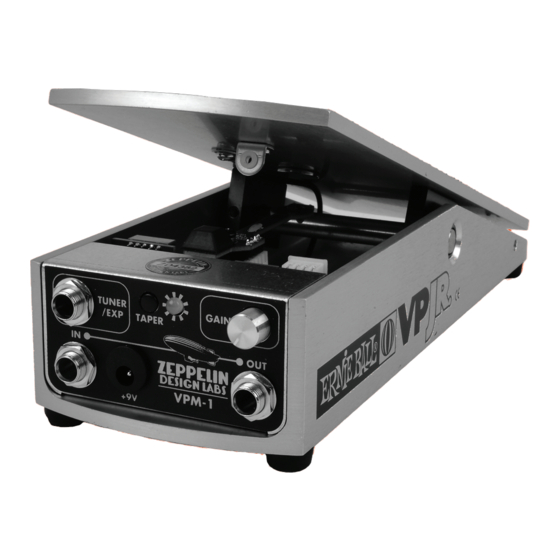
- Page 6 Figure 2: VPM-1 Chassis Front Figure 3: VPM-1 DIP Switch Locations...
-
Page 7: Audio Specifications
The actual current draw of the VPM-1 is around 50mA, so a battery probably won’t last too long if it is left plugged in, but it is a good way to troubleshoot noise issues. -
Page 8: Gain Knob
4. GAIN KNOB The VPM-1 uses a power boost converter to change the 9V DC power supplied to the circuit into18V, which allows for a significant amount of clean headroom for the audio signal. Because of this, the gain knob can add up to 14 dB of gain to the signal. In the fully counter clockwise position, the gain is at unity (no signal gain added). -
Page 9: Tuner/Exp Jack
The header labeled “TUNER” on the main PCB must be jumped in order for audio signal to be routed to this jack. This jumper is already in place if you ordered your VPM-1 pre-built. If you ever need to remove this jumper, the chassis must be taken out of the pedal in order to access it. -
Page 10: Main Board Dip Switch
7. MAIN BOARD DIP SWITCH The main board DIP switch (shown in on page 6“Figure 3: VPM-1 DIP Switch Locations” on page 6) controls several functions. “Figure 6: Main Board DIP Switch Positions” shows how to set this DIP switch to control the pedal in different ways. To access this DIP switch while the circuit board and chassis are still in the pedal, you’ll probably need to use a skinny screwdriver or tweezers. -
Page 11: Expression Upgrade
EXPRESSION UPGRADE If you opted for the expression upgrade board, the VPM-1 can be used as an expression pedal to control different parameters on other effects pedals. Using the expression function requires the use of a TRS (tip-ring-sleeve) cable between the TUNER/EXP jack and the expression input jack of the pedal you want to control. -
Page 12: Stereo Upgrade
ICs! STEREO UPGRADE The stereo upgrade board gives the VPM-1 the ability to control a stereo audio signal. This upgrade board has a second set of optocouplers on it and all the related circuitry to control the second audio path. -
Page 13: Traditional Stereo Configuration
The “reverse” function is activated when main board DIP Switch 2 is in the “ON” position. See “Figure 6: Main Board DIP Switch Positions” on page 10. This causes the VPM-1 treadle to behave in the opposite direction. In this setting, the volume is in the maximum position when the treadle’s heel is all the way down, and in the minimum position when the treadle’s toe is all the way down. -
Page 14: Appendix 1: Installing The "Ready-To-Install" Vpm-1
APPENDIX 1: INSTALLING THE “READY-TO-INSTALL” VPM-1 WHAT’S IN THE BOX Table 1: Ready-To-Install VPM-1 Bill Of Materials ZDL Part # Description Notes Ribbon Cable, 4 wire x 10cm CB-06-10 FA-93-35 Lock washer, Split Ring 3.5mm FA-12-15 Magnet PC-11-01 VPM-1 Main Board Assembly... - Page 15 VP Jr (1). Now, use your flush cutters to snip off the wires on the potentiometer (or you could just bend them back and forth until they break off) (2,3). Hang on to the screws; we will use them to install the VPM-1 main board module.
- Page 16 2. POTENTIOMETER BLOCK: a. With a #2 Philips screwdriver, remove the two screws that hold in the potentiometer block (4). Note these screws are longer than those from the jack module so keep them separate. b. Now unwind the string from the pulley to get the block out (5). c.
- Page 17 3. Unscrew the rubber foot from on top of the potentiometer block (12). Once the foot is off, remove the screw from the foot because we’ll use it later to attach the sensor board (13). INSTALLING THE VPM-1 1. RIBBON CABLE: On the long skinny sensor board there is a 4-pin header. Place the ribbon cable on the header (14).
- Page 18 Use the screw to fasten the sensor board to the potentiometer block (18). Make sure the PCB is laying perfectly flat against the top of the potentiometer block (19). Sometimes when the screw is over-tightened the back of the PCB has a tendency to lift off the block a bit, so make sure that doesn’t happen.
- Page 19 3. MAGNET: The magnet will be held on the underneath side of the treadle with the double-sided adhesive disc (TP-30-21). a. The magnet has a black marking on one side . This marking indicates the side that the (25) adhesive disc should be stuck to. Line the disc up to the magnet and press it firmly into place. b.
- Page 20 c. Attach the magnet to the end of a flat screwdriver with the adhesive disc facing up. Then peel off the backing paper on the adhesive disc (28,29). d. With the treadle wide open, place the end of the screwdriver (with the magnet still attached) on top of the circular part of the sensor board.
- Page 21 Slide the main board chassis into the VP Jr chassis and screw it in place with the short screws (34,35). That’s it! You are almost ready to go. Move on to “APPENDIX 2: CALIBRATING THE VPM-1” on page 22.
-
Page 22: Appendix 2: Calibrating The Vpm-1
VPM-1 playlist. One of the things that makes the VPM-1 very versatile is the ability to set the active range (or sweep) of the treadle to a position that is most comfortable for you. This means that you can set the minimum volume position and maximum volume position anywhere along the pedal’s range of movement. - Page 23 (4). Now tape the card in position. While holding down the TAPER button, plug the power into the VPM-1 (5). The LED should start flashing, indicating that the VPM-1 is in calibration mode. Release the button.
- Page 24 6. Repeat this process for the three remaining points on the red line (8). After the last point is recorded, press the button one more time to exit calibration mode (9). You should see the LED cycle through all the colors, indicating the calibration process is done (10). Your VPM-1 is now ready to use!
-
Page 25: Appendix 3: Replacing The Digital Potentiometer
IC. Please review “A WORD OF CAUTION” about static sensitive parts on page 15 before continuing. 1. To access the expression board you’ll need to remove the VPM-1 main board chassis from the volume pedal. Unscrew the 2 screws under the main board chassis (1). Before you unplug the ribbon cable, use a black marker to draw some orientation marks on the ribbon cable header and the main circuit board so you know which direction to plug the ribbon cable back in later (2). - Page 26 3. To make it easier to deal with the IC you can unplug the expression upgrade board from its headers on the main board (4). To remove the IC, place a small flat screwdriver under one end of the chip and very gently pry it out (5). Make sure to not bend any of its leads when doing this. 4.
- Page 27 6. Reattach the sensor board ribbon cable to the main board using the orientation marks that you made earlier (9) and re-install the main board chassis with the screws. That’s it! Your expression pedal is now ready to use!
Need help?
Do you have a question about the VPM-1 and is the answer not in the manual?
Questions and answers