Advertisement
Quick Links
Advertisement

Related Manuals for HDPlex H1 V3 Series


Summary of Contents for HDPlex H1 V3 Series
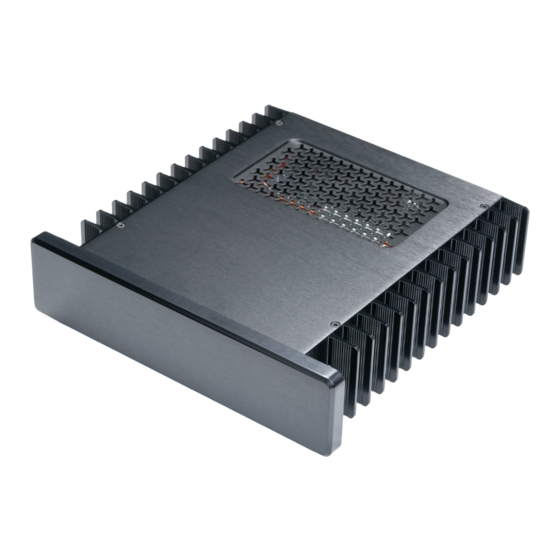
- Page 1 HDPLEX H1 V3 Series Fanless PC Chassis Installation Guide...
- Page 2 Paypal/Rü ckerstattung zu Ihrem Auftrag. Offre de remboursement HDPLEX Recevez 20 dollars US pour tout achat d'un boitier HDPLEX. Pour bé né ficier de cette offre, rien de plus simple: prenez deux ou trois photos de votre installation HDPLEX accompagné es de vos commentaires ou suggestions (dans la langue de votre choix) puis postez-les sur un blog, sur Facebook, ou sur n'importe quel forum.
-
Page 3: Package Contents
Package Contents H1 V3 Chassis Top Plate Bottom Plate Left Side Panel Right Side Panel Backplate for Mini-ITX Faceplate (Brushed Silver/Black) Four Aluminum Feet with cushion Backplate for Thin-ITX (Optional and Sold Separately) H1 V3 Installation Kit List: B: M5*8 CUP Head HEX Screw 8pcs A: M3*6 Screw 8pcs C: M4*8 Flat Head HEX Screw-Black 16pcs D: M3*8 Round Head Screw 4pcs... - Page 4 Front Audio Jack with cable Aluminum Power Button with PWR and LED cable Power Adapter Plate for 7.4*5.0mm Self Lock Connector HDPLEX H1 Fanless CPU Heatsink System H-1: M3*6 Silver Screw 4pcs H-2: M3*8 CUP Head HEX Screw Silver 8pcs...
- Page 5 H1 CPU Heatsink System Installation Install four feet with rubber cushion to the bottom plate via 4pcs M*6 HEX screw C. Install four 7mm hexagonal copper stud on the bottom plate ITX motherboard installation position and attach M3 nut to the hexagonal copper stud from the back. This will firmly lock the copper stud.
- Page 6 Install the rack on the copper baseplate using 4pcs H-1. Install the LGA115x bottom rack for Intel CPU or bottom holder for AMD AM2/AM3/FM1 socket CPU on the back of the motherboard. Remove the protection cover from the copper baseplate. For AM4 socket, the straight edge of the AMD rack should be on the outside.
- Page 7 Apply a very thin layer of thermal paste to the copper baseplate surface. Install 4pcs plastic screw holder onto the four corners. Install the copper base to the motherboard using 4pcs H-3. Do not over tighten as this will bend the rack and put too much pressure on CPU. There should be a small gap between the bottom of and motherboard surface after screws is tightened.
- Page 8 Connect SATA power, USB cable, and SODIMM memory module first. Those ports might not be accessible after heatpipes are installed. Apply a very thin layer of thermal paste to the copper plate groove using the dumbbell tool. Warning: Don't over use the thermal paste as it will decrease the thermal transfer efficiency.
- Page 9 For all Thin-ITX and mini-ITX motherboard with 24PIN connector on the front,arrange the six heatpipes following those two examples. Example 1: Example 2:...
- Page 10 For mini-ITX motherboard with 24PIN ATX connector on the side, you could install the heatpipes like this: Install the metal plate to the chassis side panel using H-4. Apply a thin layer of thermal paste on each groove on the aluminum top plate and install the aluminum top plate via 8pcs H-2.
-
Page 11: Power Supply Installation
Install the H1 backplate to the H1 V3 chassis using 4pcs Install HDPLEX 200W AC-DC on the H1 V3 bottom plate using four M3 screws included in the 200W AC-DC package. Plug HDPLEX 200W DC-ATX directly into the motherboard. External AC Adapter+HDPLEX 200W DC-ATX/400W HiFi DC-ATX Combo Install the 7.4*5.0mm Self Lock DC Jack PCB on the power adapter plate. - Page 12 Install the 400W HiFi DCATX on the H1 bottom plate using M3 screws inside the 400W HiFi DCATX package. HDPLEX 200W DC-ATX could also be installed on the H1 bottom plate using two M2*6 screws included in the 200W DC-ATX package. It connects to motherboard via the 24PIN extension cable. For H1.TODD V3 case, HDPLEX 200W DC-ATX must be installed in this position.
- Page 13 PCIE expansion card to the Thin-ITX motherboard. Riser card is not included in the H1 V3 package. Thin-ITX backplate for H1 V3 series is sold separately and is NOT included in the H1 V3 package. H1 HDD Rack and SSD Installation H1 V3 HDD rack has three SSD mounting positions.
- Page 14 B: Install one SSD horizontally using 4pcs G. Install HDD rack to the H1 side panel using 3pcs G.
- Page 15 Install two M3*5mm hexagonal copper stud and ODD Eject Button to the faceplate. Install Eject Button Circuit Board. H1.TODD supports HDPLEX 80W AC-DC+200W DC-ATX combo. HDPLEX 200W DC-ATX must be installed on the H1 bottom plate and 24PIN extension cable is required. This 24PIN extension cable is included in the H1.TODD package.
- Page 16 M2*4 screws. Install the aluminum ODD tray cover using double sided tape after making sure optical tray eject and retreat correctly. HDPLEX has designed a unique eject button connecting to the USB 2.0 onboard port to eject optical drive via OS command. The HDPLEX eject button does not rely on optical drive's own eject button.
- Page 17 For suggestions and advice on HDPLEX fanless chassis, please visit our community at https://www.hdplex.com/forum Copyright 2019 HDPLEX LTD. All rights reserved. All trademarks are the property of their respective owners. Reproduction in whole or in part without written permission is prohibited.
Need help?
Do you have a question about the H1 V3 Series and is the answer not in the manual?
Questions and answers