Table of Contents
Advertisement
Quick Links
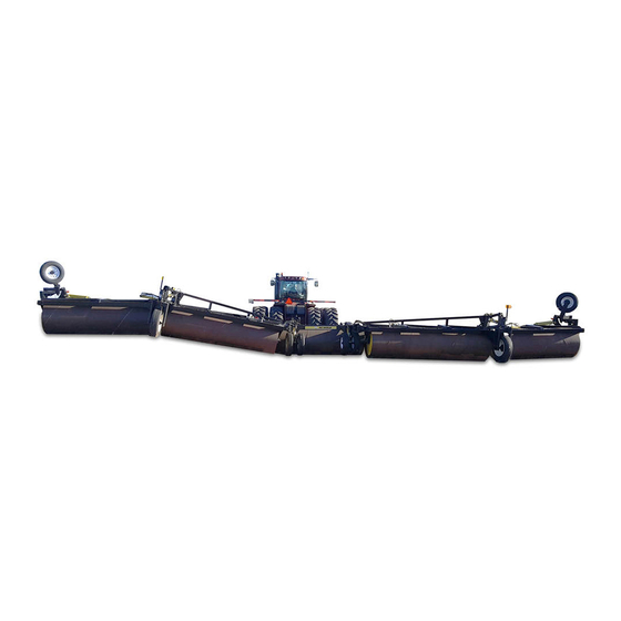
AG SHIELD
5 section LandRoller(46-70 foot)
OPERATOR'S HANDBOOK
AND PARTS MANUAL
Ag Shield Manufacturing
Box 9, Benito, Manitoba R0L 0C0
Phone 800-561-0132 or 204-539-2000
Fax 204-539-2130
E-mail address sales@agshield.com
Please visit web site at http\\:www.agshield.com
Printed in Canada
April 15 2015
REV 3
-Part No 800055
Serial no. 1215501 and up
Advertisement
Table of Contents

Related Manuals for AG SHIELD LandRoller

Summary of Contents for AG SHIELD LandRoller
- Page 1 AG SHIELD 5 section LandRoller(46-70 foot) OPERATOR’S HANDBOOK AND PARTS MANUAL Ag Shield Manufacturing Box 9, Benito, Manitoba R0L 0C0 Phone 800-561-0132 or 204-539-2000 Fax 204-539-2130 E-mail address sales@agshield.com Please visit web site at http\\:www.agshield.com Printed in Canada April 15 2015...
- Page 2 PAGE 2...
-
Page 3: Phone 1-800-561-0132 Or 204-539-2000 Fax 204-539-2130
Warranty Registration Form - Warranty registration must be filled out by the dealer at the time of delivery, and emailed, faxed, or mailed to Ag Shield within 10 days of customer invoice to validate warranty. Machine type- Model - Delivery Date e.g. - Page 4 PAGE 4...
-
Page 5: Table Of Contents
5.8. REPLACING THE OUTER CASTER WHEEL................29 5.9. LUBRICATION ........................... 30 SPECIFICATIONS – 5 SECTION LANDROLLERS ............31 PARTS LIST 3 SECTION LANDROLLER ................. 32 7.1. TOW HITCH 3 SECTION UNITS- 800450 .................. 32 7.2. CENTER FRAME ASSEMBLY ....................33 7.3. -
Page 6: Introduction And Sign-Off Form
Ag Shield follows the general safety standards specified by the American Society of Agricultural Engineers (ASAE) and the Occupational Safety and Health Administration OSHA). Anyone who will be operating and/or maintaining the Ag Shield LandRoller must read and clearly understand ALL Safety, Operating, and Maintenance information presented in this manual. -
Page 7: Safety
This Safety Alert symbol means: The Safety Alert symbol identifies important ATTENTION! BECOME ALERT! safety messages on the Ag Shield Recon 300 YOUR SAFETY IS INVOLVED! and in the manual. When you see this symbol, be alert to the possibility of personal injury or death. -
Page 8: Safety Overview
3.2. GENERAL SAFETY YOU are responsible for the SAFE operation and 1. Read and understand the maintenance of your Ag Shield Recon 300. YOU must Operator's Manual and all ensure that you and everyone who is going to operate, safety signs before operating,... -
Page 9: Maintenance Safety
3. Replace any worn, cut, abraded, flattened or before working with, maintaining or operating the crimped hoses and steel lines. LandRoller. 4. Do not attempt any makeshift repairs to the 2. Stop the tractor engine, place all controls in hydraulic lines, fittings or hoses by using tape, neutral, set park brake, remove ignition key, wait clamps or cements. -
Page 10: Storage Safety
7. Always use hazard warning flashers on the Recon 300 when transporting unless prohibited by law. 6. Do not allow riders on the LandRoller or tractor during operation or transporting. 3.10. REFUELING SAFETY 7. Clear the area of all bystanders, especially children, before starting. -
Page 11: Safety Decals
3.13. SAFETY DECALS Become familiar with these decals, and the hazards they are marking. The decal locations are detailed in this section below part # 113552 high pressure fluid Part # 116116 Danger pinch point hazard... - Page 12 113555 warning pinch point hazard FIGURE 1 #116140 YELLOW AND WHITE AG SHIELD STRIPES FIGURE 2 DECAL #116141 YELLOW AND WHIRE STRIPES AG SHIELD FIGURE 3 116142 "LANDROLLER" YELLOW AND WHITE STRIPES FIGURE 4 DECAL AGSHIELD MFG SIDE REAR OF HITCH 3X36 #116107...
- Page 13 FIGURE 6 DECAL 12-62-5 FIGURE 7 DECAL 12-66 5 FIGURE 8 DECAL 12-70-5 part # 800819 part# 800818 part red and white tape # 803088 for cut length – bulk part #...
- Page 14 Serial plate part number #800817 FIGURE 9 DANGER DECAL #116116 WARNING OVERHEAD HAZARD #113549...
-
Page 17: Setup From Shipping Mode
4. Setup from Shipping Mode 4.1. TOWED OUT SHIPPING Towed out units should be field ready, Check wheel bearings for correct adjustment, grease and go to the field 4.2. TRUCK SHIPPING... -
Page 18: Operations
FIGURE 10 WINGS TRAILING DIRECTLY BEHIND wing move from behind the center section to the field position. This is different from the Ag Shield 3. Operate Lever 2 to raise the rollers up ALL PowerFold option where the wheels are first... - Page 19 6. Rotate the 2 center wheel locks over center to the rear. FIGURE 13 OUTER WHEEL HEIGHT LOCKED 9. Remove the height locks H from the FIGURE 12 CENTER WHEEL UNLOCKED FOR cylinders at the inner wheels. Place the lock FIELD on storage point I during field operation.
- Page 20 STRAIGHT UNTIL THE WINGS START TO FOLD THEN SLOWLY ANGLE THE WHEELS TO COMPLETE THE FOLD. 16. Move Lever 1 to rotate the wheels to the field position. When the wheels are in road position the flag above the wheel will point in the direction of the tire.
- Page 21 18. Observe that the diagonal pulling arms are 24. On the middle transport weldment we use a fully rotated into the slots on front corner of check valve to ensure the wheel stays in both ends of the center section. To get position.
-
Page 22: Easifold" Folding From Field To Road Procedure
10. Move over center cylinder lock from C to B 5.2. “EASIFOLD” FOLDING FROM Place the pin into hole A to retain the locks. FIELD TO ROAD PROCEDURE 1. Chose a reasonably level location with no bystanders or children in the vicinity. 2. - Page 23 15. Do all locks the same for the right side of machine. 16. Enter the cab, 17. Drive forward, observing that the wings trail in behind the center section to the normal 13.5 foot wide transport width. 18. You may adjust the angle of the wings in 13.
-
Page 24: Powerfold Folding From Road To Field
ROAD TO FIELD POWERFOLD SECTION NOT COMPLETE Rev1a The Ag Shield PowerFold option has cylinder A to lower the spindle onto the tire, cylinder B to rotate the wheel between field and road positions, and cylinder C for height adjustment . - Page 25 8. Rotate the center wheel lock over center 12. Move lever 2 to lower the rollers to the to the rear. ground, and raise the wheels completely up into field operation position. 13. Observe that the diagonal pulling arms are fully rotated into the slots on front corner of both ends of the center section.
-
Page 26: Adjusting Powerfold Sequence Valve Operating Pressures
See “A” The PowerFold option allows you to park the Figure 22 LOCKED FOR ROAD LandRoller on one spot and move the wings to field TRANSPORT position. It works by building up to a preset pressure in the cylinders holding the tire against the drive spindle, before oil flow is delivered to the hydraulic motors. -
Page 27: Water Filling Roller Tank
Imperial gallons per foot, 66 USG per foot, 250 liters Scraper option – weld on per foot, or 820 liters /meter Except by special request Ag Shield LandRollers are not designed to be transported while filled. Damage to machine components will occur if a water filled roller is even attempted to be raised hydraulically to road position. -
Page 28: Acre Meter Option
8) Touch right “B” 8 times to advance to “8” in simplified instructions to set to 88.0 for a 45 foot the fourth digit. LandRoller are: 9) Do nothing for 10-20 seconds, and front 1) Hold magnet on the left position- “A” – in 6 screen will come up reading 88.0 revs acres in... -
Page 29: Replacing The Outer Caster Wheel
5.8. REPLACING THE OUTER CASTER WHEEL Only necessary if having to replace the outer caster wheels. 1) It is important that before you install the caster wheel that it must have all sharp edges removed or it will cut the O ring as it is inserted into the bushing. Both edges where the lines are will need to be smoothed out. -
Page 30: Lubrication
5.9. LUBRICATION Grease all pivot points daily, or 8 hours of operation. Grease the bearings on the rollers weekly or 50 hours, some places annually No other lubrication is required... -
Page 31: Specifications - 5 Section Landrollers
6. SPECIFICATIONS – 5 Section LandRollers SPECIFICATION 46 foot 5 section 62 foot 3 section 70 foot 5 section Weight Dry(shipping) Operating(field) Shipping space partially knocked down Length ( front hitch to tip of side deflector) Width Tire Size Rim Size Tire pressure Wheel nut size Wheel nut torque... -
Page 32: Parts List 3 Section Landroller
7. PARTS LIST 3 SECTION LANDROLLER 7.1. TOW HITCH 3 SECTION UNITS- 800450 800022 Land Roller 62ft Assembly Parts List Parts List ITEM QTY PART NUMBER ITEM QTY PART NUMBER 1 113803 Flat Mount Hose Holder 1 801311 Inner Wheel Cyl Lock... -
Page 33: Center Frame Assembly
7.2. CENTER FRAME ASSEMBLY... -
Page 34: Inner Wing Frame Assembly
7.3. INNER WING FRAME ASSEMBLY... -
Page 35: Section Knuckles Front Hitch
7.4. 5 SECTION KNUCKLES FRONT HITCH 800022 Land Roller 62ft - Center Detail A 801220 Hitch Wldt 5 Section 801737 Center Section Assy 5S 802006 Wing Assy Inner 5S RH 800420pin wldt 1-1/4 x 7-5/8 801726 Outer Wing Assy 62ft 5S RH 801753 Inner Wheel Assy RH 801728 Outer Wing Assy 62ft 5S LH 801754 Inner Wheel Assy LH... -
Page 36: Center Section 5 Section 62 Foot Rear View
7.5. CENTER SECTION 5 SECTION 62 FOOT REAR VIEW 801737 CENTER SECTION ASSEMBLY (front) B ACK VIEW 48.1 44.5 48.3 44.2 48.2 48.4 44.4 48.5 48.1 ITEM QTY PART NUMBER ITEM QTY PART NUMBER 800999 Bearing DT 2-1/2" UCF213-40 102125 nut nylok 1/2" nc gr5 pltd 800106 Shaft Roller End 100707 bolt 1/2 X 4 gr5 pltd nc 803248 Shaft Roller End Threaded RH... -
Page 37: Center Section 5 Section 62 Foot End Of Roller
7.6. CENTER SECTION 5 SECTION 62 FOOT END OF ROLLER... -
Page 38: Center Section Wheels Hydraulics
7.7. CENTER SECTION WHEELS HYDRAULICS... -
Page 39: Ft 5 Section Rh Wing
7.8. 62 FT 5 SECTION RH WING... -
Page 40: Ft 5 Section Lh Wing
7.9. 62 FT 5 SECTION LH WING... -
Page 41: Outer Frame / Roller 5 Section 62 Ft
7.10. OUTER FRAME / ROLLER 5 SECTION 62 FT... -
Page 42: Outer Wheel Assembly
7.11. OUTER WHEEL ASSEMBLY 804191 WHEEL ASSY OUTER CASTER ITEM Q TY PART NUMBER ITEM Q TY PART NUMBER 105607 grease zerk 113986 tire whl assy 8 bolt 6 x 16 5.15 800724 washer poly 22 caster 5S outer pilot 128113 3 1-4 vinel cap 800748 caster 5S top nut wldt 114613 washer bronze 325OD x 25ID... -
Page 43: Inner Wheel Assembly Original Powerfold Option
7.12. INNER WHEEL ASSEMBLY ORIGINAL POWERFOLD OPTION 801754 Inner Wheel Assembly LH ITEM PART NUMBER 802059 socket castor LH wldt 802049 castor wheel LH wldt 802065 Disc Poly Slider 802200 hub spindle 8 bolt wldt 113989 tire wheel assy 255 22.5 on 8-8-6 x 8.25 114422 2 211 ductile flge brg 2 assy 102127 nut nylok 5/8"... -
Page 44: Spindle And Hub Parts 8 Bolt-113686
7.13. SPINDLE AND HUB PARTS 8 BOLT-113686... -
Page 45: Hydraulic Schematic 5 Section 62 Ft Boom
7.14. HYDRAULIC SCHEMATIC 5 SECTION 62 FT BOOM... -
Page 46: Warranty
2. Ag Shield’s obligation under this warranty is limited to the supplying of parts to replace those which are defective due to factory workmanship or material. - Page 47 This page intentionally blank...
- Page 48 I CERTIFY THAT THE INFORMATION IS ACCURATE AND PARTS DATE PARTS RECD RECD BY THAT THE PARTS WERE REPLACED ON THE MACHINE LABOUR ITEMS TO SUPPLIERS TOTAL SHADED AREAS AG SHIELD USE ONLY ---PLEASE ADD DETAILS FOR ITEM NUMBERS ON BACK...
- Page 49 ITEM ITEM The end...
-
Page 50: Powerfold Option Instructions
The PowerFold option allows you to park the LandRoller on one spot and move the wings to field Field installation position. It works by building up to a preset pressure in... - Page 51 B) the curve of tire fits precisely into the curve of the drive spindle when under pressure, 10) IF it does not fit perfectly when under pressure, shim the spindle end ways using the machinery bushing, and spacers to hold the spindle in precisely the correct position.
- Page 52 FIGURE 27 POWERFOLD WHEEL SYSTEM FIGURE 28 DRIVE SPINDLE WITH SPACERS & MACHINERY BUSHINGS TO SHIM TO CENTER...
- Page 53 FIGURE 29 POWERFOLD KIT CONTENTS FIGURE 30 EASIFOLD WHEEL - HYDRAULIC TURN – NOT POWERFOLD-- LOCKED...
Need help?
Do you have a question about the LandRoller and is the answer not in the manual?
Questions and answers