Table of Contents
Advertisement
Quick Links
Advertisement
Table of Contents

Subscribe to Our Youtube Channel
Related Manuals for IMI NORGREN 54D


Summary of Contents for IMI NORGREN 54D
- Page 1 Electronic Pressure Sensor Operation manual 54D-xxxxx-DD0-xx 2 x PNP...
-
Page 2: Table Of Contents
Electronic Pressure Sensor 54D Operation manual Content 1. Preliminary note 1.1 Symbols used 2 Safety information 3. Functions and features 4. Function 4.1 Processing of the measured signals 4.2 Switching function 4.3 Diagnostic function 5. Installation 5.1 Mounting accessories 5.2 DIN rail mounting 5.3 Panel mounting... - Page 3 Electronic Pressure Sensor 54D Operation manual 9.4 Service functions 9.4.1 Read min/max values for the system pressure 9.4.2 Reset all parameters to factory setting 10. Operation 10.1 Read set parameters 10.2 Error indications 10.3 Setting ranges 11. Factory setting 7503761000000050 05/2019...
-
Page 4: Preliminary Note
Electronic Pressure Sensor 54D Operation manual Preliminary note 1.1 Symbols used ► Instructions > Reaction, result […] Designation of keys, buttons or indications → Cross-reference Important note Non-compliance can result in malfunction or interference. 2. Safety instructions Please read this document prior to set-up of the unit. Ensure that the product is suitable for your application without any restrictions. -
Page 5: Function
Electronic Pressure Sensor 54D Operation manual 4. Function 4.1 Processing of the measured signals The unit displays the current system pressure. It generates 2 output signals according to the parameter setting. OUT1 Switching signal for limit value OUT2 2 options •... -
Page 6: Diagnostic Function
Electronic Pressure Sensor 54D Operation manual 4.3 Diagnostic function Output 2 is used as diagnostic output based on the DESINA specification if [ou2] = [diA]. If there is no fault, the output is switched and carries Ub+ . ... -
Page 7: Din Rail Mounting
Electronic Pressure Sensor 54D Operation manual 5.2 DIN rail mounting DIN rail TH 35-7.5 to EN 60715 ► Fix the mounting clip (1) with the M4 x 35 screws (2) to the flange. Maximum tightening torque: 0,5 Nm. ► Hook the unit into the DIN rail and clip it into place. -
Page 8: Electrical Connection
Electronic Pressure Sensor 54D Operation manual Electrical connection The unit must be connected by a qualified electrician. The national and international regulations for the installation of electrical equipment must be adhered to. Voltage supply according to EN 50178, SELV, PELV. -
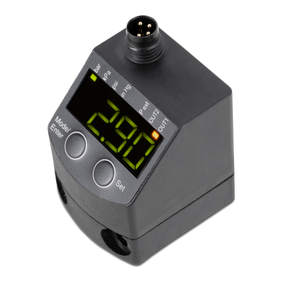
Page 9: Operating And Display Elements
Electronic Pressure Sensor 54D Operation manual Operating and display elements Mode/Enter 1 to 8: Indicator LEDs LED 1 to LED 4 system pressure / differential pressure in the unit of measurement which is indicated on the label. LEDs 5, 6 not used. -
Page 10: Menu
Electronic Pressure Sensor 54D Operation manual Menu 8.1 Menu structure 7503761000000050 05/2019... -
Page 11: Explanation Of The Menu
Electronic Pressure Sensor 54D Operation manual 8.2 Explanation of the menu SP1/rP1 Upper / lower limit value for system pressure at which OUT1 switches. FH1/FL1 Upper / lower limit for the acceptable range (monitored by OUT1). SP2/rP2 Upper / lower limit value for system pressure at which OUT2 switches. -
Page 12: Parameter Setting
Electronic Pressure Sensor 54D Operation manual Parameter setting During parameter setting the unit remains in the operating mode. It continues to monitor with the existing parameters until the parameter setting has been completed. 9.1 Parameter setting in general Each parameter setting requires 3 steps: Select parameter ►... - Page 13 Electronic Pressure Sensor 54D Operation manual Change from menu level 1 to menu level 2: ► Press [Mode/Enter] until [EF] is displayed.. If the submenu is protected with an access code, [cod1] is displayed. Mode/Enter ► Press [Set] and keep it pressed until the valid code no.
-
Page 14: Set Output Signals
Electronic Pressure Sensor 54D Operation manual 9.2 Set output signals 9.2.1 Set the unit of measurement for system pressure ► Select [Uni] and set the unit of measurement: [bAr], [kPa], [PSi], [inHg] 9.2.2 Set the output function ► Select [OU1] and set the function:... -
Page 15: Set Damping For The Switching Outputs
Electronic Pressure Sensor 54D Operation manual 9.3.2 Set damping for the switching outputs ► Select [dAP] and set the value. dAP value = response time between pressure change and change of the switching status in milliseconds. The following fixed values can be set; they define the switching frequency (f in... -
Page 16: Zero-Point Calibration
Electronic Pressure Sensor 54D Operation manual 9.3.4 Zero-point calibration ► Select [coF] and set a value between -2 % and 2 % of the measuring span. The internal measured value "0" is shifted by this value. As an alternative: Automatic adjustment of the offset in the range 0 bar ± 2 % of the measuring span. - Page 17 Electronic Pressure Sensor 54D Operation manual 9.4 Service functions 9.4.1 Read min/max values for the system pressure ► Select [Hi] or [Lo], briefly press [Set]. [Hi] = maximum value, [Lo] = minimum value. Delete memory: ► Select [HI] or [LO].
- Page 18 Electronic Pressure Sensor 54D Operation manual 10.3 Setting ranges SPx / FHx rPx / FLx PQ7809 -0,98 1,00 -0,99 0,99 0,01 -14,2 14,6 -14,4 14,4 inHG -28,8 29,7 -29,1 29,4 PQ7834 -0,90 10,00 -0,95 9,95 0,05 1000 inHG PQ7809 --> 54D-V101-DD0-AA PQ7834 -->...
- Page 19 Electronic Pressure Sensor 54D Operation manual 7503761000000050 05/2019...
- Page 20 Electronic Pressure Sensor 54D Operation manual The data specified above only serve to describe the product. No statements concerning a certain condition or suitability for a certain application can be derived from our information. The given information does not release the user from the obligation of own judgement and verification.
Need help?
Do you have a question about the 54D and is the answer not in the manual?
Questions and answers