
Subscribe to Our Youtube Channel
Related Manuals for BERGHOF DC1005


Summary of Contents for BERGHOF DC1005
- Page 1 Z U N D E L H o l d i n g E n t e r p r i s e DIALOG CONTROLLER DC1005 DC1010 DC1012 V.1.3 Equipment Manual...
- Page 2 General Information on this Manual Content: This manual describes the DIALOG CONTROLLER DC1005 and its modifications. The product-related information contained herein was up to date at the time of publication of this manual. Completeness: This manual is complete only in conjunction with the user manual entitled 'Introduction to CANtrol Automation System’...
- Page 3 BERGHOF Automation DIALOG CONTROLLER Update Version Date Subject 22.09.06 First version Inexistent 31.05.07 Dimensions updated under “Technical Specifications” and in the graphs. Plug/unplug cycles added to the “USB Pin Assignment” section of the technical specifications. Description, “Chemical Resistance for Touch Screens” and "I/O- Modules"...
- Page 4 DIALOG CONTROLLER BERGHOF Automation This page intentionally blank. DC1000_HB_en_2D0982003ZD00.doc...
-
Page 5: Table Of Contents
CE Notice (European Union) ....................13 1.8. Transport and Setup ..........................14 PRODUCT DESCRIPTION ..................15 2.1. Identification ............................17 2.2. DIALOG CONTROLLER DC1005 / DC1010 / DC1012 Construction..........18 2.2.1. Block Circuit Diagram ......................18 2.3. Technical Specifications, DC1005 ......................19 2.3.1. DC1005 Front View .........................21 2.3.2. - Page 6 DIALOG CONTROLLER BERGHOF Automation 2.7.7. E-Bus............................37 2.7.8. Connections for Expansion Ports.................... 37 2.8. SD-Card ..............................38 DIALOG CONTROLLER OPERATION..............39 3.1. Commissioning............................ 39 3.2. Function Selection, Indicators, Diagnostics..................39 3.2.1. Status Indicators ........................39 3.3. Service Menu ............................41 3.3.1.
- Page 7 BERGHOF Automation DIALOG CONTROLLER Digital input operating ranges ....................66 5.1.5. Digital Outputs, Positive Switched ...................67 Basic output circuit diagram.....................67 Digital output data ........................68 Digital output overload behavior ....................69 5.1.6. Digital Input/Output Pin Assignments ..................70 Encoder interface........................70 5.2. PROFIBUS MASTER Card ........................71 5.2.1.
- Page 8 DIALOG CONTROLLER BERGHOF Automation This page intentionally blank. DC1000_HB_en_2D0982003ZD00.doc...
-
Page 9: General Information
BERGHOF Automation General General Information This equipment manual is intended for qualified personnel and contains information Documentation regarding the mounting, installation, commissioning and maintenance of the DIALOG CONTROLLER. The information contained in this manual is subject to change without prior notice. -
Page 10: Hazard Categories And Terminology
General BERGHOF Automation 1.2. Hazard Categories and Terminology Immediate danger Failure to observe the information indicated by this warning will result in death, serious injury or extensive property damage. Potential danger Failure to observe the information indicated by this warning may result in death, serious injury or extensive property damage. -
Page 11: Qualified Personnel
BERGHOF Automation General 1.3. Qualified Personnel Only qualified personnel may install, operate and maintain the DIALOG CONTROLLER. Within the context of this documentation and the safety information it contains, qualified personnel constitutes trained specialists who have the authority to mount,... -
Page 12: Basic Safety Measures
General BERGHOF Automation 1.5. Basic Safety Measures Before beginning work on the DIALOG CONTROLLER you must always; Working on the DC • First ensure that the equipment is in a safe state; • Then first switch the DC off, followed by the equipment, and;... -
Page 13: Use As Prescribed
BERGHOF Automation General 1.6. Use as Prescribed This is a modular automation system based on the CANbus, intended for industrial control applications within the medium to high performance range. The automation system is designed for use within Overvoltage Category I... -
Page 14: Transport And Setup
General BERGHOF Automation 1.8. Transport and Setup Please note the specified storage conditions in the Section, “Technical Specifica- tions”. Protect the DIALOG CONTROLLER against extreme mechanical stress during Transport transport. Always transport the DIALOG CONTROLLER in its original packaging. The built-in components are extremely sensitive to jarring and strong vibrations. -
Page 15: Product Description
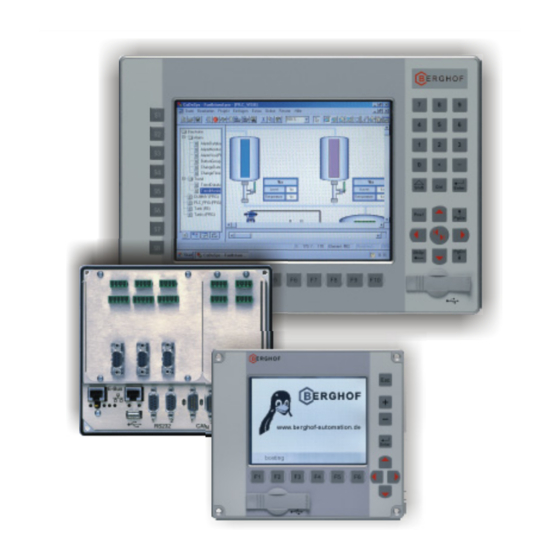
BERGHOF Automation Product Description Product Description The DIALOG CONTROLLER is a real-time control module with a display and a Short description broad spectrum of data interfaces. The module can be programmed in 'C' or in accordance with IEC 61131-3 (CoDeSys 2.3). - Page 16 Product Description BERGHOF Automation The DIALOG CONTROLLER’s I/O level can be expanded via the E-bus socket to E-bus extension include up to seven E-bus subscribers. The device is equipped with three expansion slots for expansion cards (e.g., I/O Expansion slots cards) with the associated SPI interface.
-
Page 17: Identification
BERGHOF Automation Product Description 2.1. Identification DIALOG CONTROLLER Product DC10xx Type The identification code provides a key to the DIALOG CONTROLLER (refer to the Identification key nameplate). The code can be read as follows. 10 11 12 13 14 15 16 ... -
Page 18: Dialog Controller Dc1005 / Dc1010 / Dc1012 Construction
Product Description BERGHOF Automation 2.2. DIALOG CONTROLLER DC1005 / DC1010 / DC1012 Construction 2.2.1. Block Circuit Diagram Display Unit Touch / Inverter Keyboard Display Front FRONT Controller Grafik Flash +24 V BASIS 2VF100233DG00_en.cdr DC1000_HB_en_2D0982003ZD00.doc 2VF100107FE03.doc... -
Page 19: Technical Specifications, Dc1005
BERGHOF Automation Product Description 2.3. Technical Specifications, DC1005 DIALOG CONTROLLER Product identification Display type: Input: Designation: Part no.: Monochrome (STN) Keyboard DC1005M K MP266 270000100 Monochrome (STN) Touchpad DC1005M T MP266 270000000 Color (CSTN) Touchpad DC1005C T MP266 270000200 Color TFT... - Page 20 Product Description BERGHOF Automation Power supply (24 V power pack) +24 VDC (-15% / +20%) SELV Supply voltage max. alternating component: 5% Current consumption Typically 1.0 A; max. 2.0 A at +24 VDC Fusing depending on the I/O load, max. 12A...
-
Page 21: Dc1005 Front View
BERGHOF Automation Product Description 2.3.1. DC1005 Front View Power Status-LED Front-USB 2VF100229DG00. cdr 2.3.2. DC1005 Rear View Abdeckung Erweiterungssteckplätze Cover Interface Boards Geräte-Anschlüsse Frontplatte Frontpanel Connections 2VF100230DG00.cdr 2VF100107FE03.doc DC1000_HB_en_2D0982003ZD00.doc... -
Page 22: Dc1005 Dimensions
Product Description BERGHOF Automation 2.3.3. DC1005 Dimensions Dimensions are identical for units equipped with either a keyboard or a touchpad. max. 52 Enter Freie Luftzirkulation free air circulation Alle Maße in [mm] DC1005M K Freiraum / clearance > 20 mm All dimensions in [mm] max. -
Page 23: Dc1005 Panel Cutout
BERGHOF Automation Product Description 2.3.4. DC1005 Panel Cutout Installation instruction: Only install the DIALOG CONTROLLER on a level surface. The support points on the DIALOG CONTROLLER may not deviate from one an- other by more than +/-0.5 mm. If the DIALOG CONTROLLER is nonetheless mounted on a base which is not level, mechanical tension can result in cracks in the front panel. -
Page 24: Technical Specifications, Dc1010
Product Description BERGHOF Automation 2.4. Technical Specifications, DC1010 DIALOG CONTROLLER Product identification Display type: Input: Designation: Part no.: Color TFT Keyboard DC1010T K MP400 270000800 Color TFT Touchpad DC1010T T MP400 270000400 Display Diagonal measurement 10.4” Resolution 640 x 480 pixels (VGA) - Page 25 BERGHOF Automation Product Description Power supply(24 V power pack) +24 VDC (-15% / +20%) SELV Supply voltage max. alternating component: 5% Current consumption Typically 1.0 A; max. 2.0 A at +24 VDC Fusing depending on the I/O load, max. 12A...
-
Page 26: Dc1010 Front View
Product Description BERGHOF Automation 2.4.1. DC1010 Front View Front-USB 2VF100241DG00. cdr 2.4.2. DC1010 Rear View Abdeckung Erweiterungssteckplätze Cover Interface Boards Geräte-Anschlüsse Frontplatte Connections Frontpanel 2VF100242DG00.cdr DC1000_HB_en_2D0982003ZD00.doc 2VF100107FE03.doc... -
Page 27: Dc1010 Dimensions
BERGHOF Automation Product Description 2.4.3. DC1010 Dimensions Dimensions are identical for units equipped with either a keyboard or a touchpad. max. 77 Shift Ctrl Enter Pos1 PgUp BkSp PgDn Alle Maße in [mm] / All dimensions in [mm] Freie Luftzirkulation... -
Page 28: Technical Specifications, Dc1012
Product Description BERGHOF Automation 2.5. Technical Specifications, DC1012 DIALOG CONTROLLER Product identification Display type: Input: Designation: Part no.: Color TFT Keyboard DC1012T K MP400 270000700 Color TFT Touchpad DC1012T T MP400 270000600 Display Diagonal measurement 12.1” Resolution 800 x 600 pixels (VGA) - Page 29 BERGHOF Automation Product Description Power supply (24 V power pack) +24 VDC (-15% / +20%) SELV Supply voltage max. alternating component: 5% Current consumption Typically 1.0 A; max. 2.0 A at +24 VDC Fusing depending on the I/O load, max. 12A...
-
Page 30: Dc1012 Front View
Product Description BERGHOF Automation 2.5.1. DC1012 Front View Front-USB 2VF100272DG00. cdr 2.5.2. DC1012 Rear View Abdeckung Erweiterungssteckplätze Cover Interface Boards Geräte-Anschlüsse Frontplatte Connections Frontpanel 2VF100242DG00.cdr DC1000_HB_en_2D0982003ZD00.doc 2VF100107FE03.doc... -
Page 31: Dc1012 Dimensions
BERGHOF Automation Product Description 2.5.3. DC1012 Dimensions Dimensions are identical for units equipped with either a keyboard or a touchpad. max. 77 Ctrl Shift Enter Pos1 PgUp BkSp PgDn Alle Maße in [mm] / All dimensions in [mm] Freie Luftzirkulation... -
Page 32: Mounting And Connection
Product Description BERGHOF Automation 2.6. Mounting and Connection 2.6.1. Mounting Box wrench, Allan key (7 mm) or open-end wrench SW Required tools The DIALOG CONTROLLER is equipped with approx. 15 mm-long, M 4, Securing welded-on stud bolts. The unit is secured using U washers, spring washers/lock washers and nuts (M 4). -
Page 33: Pin Assignment
BERGHOF Automation Product Description 2.7. Pin Assignment 2.7.1. Pin Overview 2VF100231DG00.cdr 2.7.2. Power Supply A power pack to provide 24 VDC (-15% / +20%) input voltage is built into the Internal power pack DIALOG CONTROLLER. The power pack is equipped with internal polarity rever- sal protection and a current at make limiter. -
Page 34: Usb
Product Description BERGHOF Automation 2.7.4. USB Devices equipped with USB interfaces can be connected to the two USB master ports (Rev. 1.1). The USB on the back (X3) and the front USB (under the IP65 cover) are connected via an internal USB hub. -
Page 35: Can Bus
BERGHOF Automation Product Description 2.7.5. CAN Bus The two CAN ports (CAN0/CAN1) comply with the ISO 11898 standard and can be operated up to a maximum baud rate of 1 MBit/s. The smallest CAN baud rate that can be set is 50 kBit/sec. In addition, the X6 interface (CAN0) is equipped with a potential isolation. -
Page 36: Serial Ports
Product Description BERGHOF Automation 2.7.6. Serial Ports In all, the module is equipped with three serial communications interfaces, each of which is connected using a 9-pin Sub-B socket. X8 is a potential isolated RS485 in- terface, while two RS232 ports are available at X4/X5. -
Page 37: E-Bus
BERGHOF Automation Product Description 2.7.7. E-Bus The E-bus (X1) allows up to seven E-bus subscribers to be connected to the DIALOG CONTROLLER. Please note that, due to their function, some E-bus mod- ules represent two E-bus subscribers, e.g., QDIO-E 16/16/Z2. -
Page 38: Sd-Card
Product Description BERGHOF Automation 2.8. SD-Card The SD card must not be plugged in or unplugged while the DIALOG CONTROLLER is operating as this would result in functional errors with the DIALOG CONTROLLER! The SD card may only be installed or removed when the DIALOG CONTROLLER... -
Page 39: Dialog Controller Operation
BERGHOF Automation Operation DIALOG CONTROLLER Operation Never plug in, apply, disconnect or touch connections while the device is operating! This could result in malfunction or destruction of the device. Before working on the modules, always switch all infeeds to them off; including infeeds from con- nected peripheral devices such as remote-feed encoders, programming devices, etc. - Page 40 Operation BERGHOF Automation Four operating status LEDs provide information about the current status of the po- Status LED wer supply, the module mode as well as fault and error messages. Logical state PWR (green) ON = Correct supply voltage to the module electronics...
-
Page 41: Service Menu
BERGHOF Automation Operation 3.3. Service Menu The DIALOG CONTROLLER’s service menu allows the user to define and exam- Functional scope ine device and communications parameters as well as device states. It also repre- sents a valuable service and commissioning aid. The service menu thus permits setting definition at the Ethernet interface and diagnostics functions in case of er- rors to be simplified and accelerated. -
Page 42: Using The Service Menu
Operation BERGHOF Automation 3.3.1. Using the Service Menu In DIALOG CONTROLLERs with a built-in touch screen, the service menu can be Touch screen operated directly via screen input. If the DIALOG CONTROLLER is equipped with a keyboard, the following keys are... -
Page 43: Parameter Window
BERGHOF Automation Operation 3.3.2. Parameter Window Parameter window Checking and setting options are accessed through this window section. structure The following four menu items are available for selection: • IP Config to check and adjust Ethernet parameters; • PLC to check and operate the PLC;... - Page 44 Operation BERGHOF Automation Ethernet Check and adjust the network mask. “NET MASK” Net mask: The “+/-” keys can be used to adjust and set each individual network mask byte. The “Save Mask” button is then used to sa- ve the settings. New settings will only take effect after a restart! The “EXIT”...
- Page 45 BERGHOF Automation Operation Ethernet Check and adjust the communications pa- “LINK PARAM” rameters. Link Mode: Auto: Automatic parameter setting negoti- ated among the communications parameters (default setting). The default settings should only be changed under special circumstances (e.g., communi- cations problems).
-
Page 46: Plc" Service Menu
Operation BERGHOF Automation “PLC” service menu Change the PLC state. PLC “RESET PLC” “RESET PLC” Command for the PLC program. This command can be used to acknowledge an error which has occurred. The prerequi- site for such an acknowledgement is that the “RUN PLC”... -
Page 47: Info" Service Menu
PC using the integrated “Web Con- figuration” where it can then be saved and sent to BERGHOF. The individual event logger messages as well as the web configuration are ex- plained in the “CANtrol PPC System In- troduction”... -
Page 48: Display" Service Menu
Operation BERGHOF Automation “Display” service menu Status display or contrast and backlighting Display adjustment. Display “Contrast” DIALOG CONTROLLERs with STN/CSTN displays The “+/-” keys can be used to adjust the contrast. Changes are applied immediately and will remain in effect until the next restart, even if you leave the menu with the “EXIT”... -
Page 49: Plc Window
BERGHOF Automation Operation 3.3.3. PLC Window The following PLC states can be displayed on Line 1 in the PLC window: Display Description Operating mode selection switch S1 is set to the STOP position. STOP SWITCH ACTIVE The PLC program can only be started with a programming tool if S1 is set in the RUN position. -
Page 50: Decommissioning
Operation BERGHOF Automation 3.4. Decommissioning 3.4.1. Disposal The DIALOG CONTROLLER must be disassembled into its component parts for Disassembly disposal. All metal components can be disposed of as recyclable metal. All electronic components such as PCBs, drives, etc. must be set aside and dis- Electronic waste posed of separately. -
Page 51: Chemical Resistance
BERGHOF Automation Chemical Resistance Chemical Resistance 4.1. Resistance of the Touch Screen The active area of the touch screen is resistant to the following chemicals if ex- posed to them for a period of one hour at a temperature of 21 °C:... -
Page 52: Resistance Of The Front Foil Sheeting To Chemicals
Chemical Resistance BERGHOF Automation 4.2. Resistance of the Front Foil Sheeting to Chemicals 4.2.1. General Resistance of the Foil Sheeting Material AUTOTEX is based on a polyester foil sheet with a biaxial arrangement and there- fore exhibits better resistance to solvents. It is stronger and more durable than other sheeting materials such as polycarbonate or PVC, commonly employed for touch pads and front face panels. -
Page 53: Resistance To Household Chemicals
BERGHOF Automation Chemical Resistance 4.2.2. Resistance to Household Chemicals AUTOTEX is resistant to the following products and will exhibit no visible damage for exposure periods of 24 hours at 50 °C: Top Job Grape juice Ariel Ajax Jet Dry Milk... - Page 54 Chemical Resistance BERGHOF Automation This page intentionally blank. DC1000_HB_en_2D0982003ZD00.doc 2VF100123FE00.doc...
-
Page 55: Extension Modules
BERGHOF Automation Extension Modules Extension Modules Steckplatzbezeichnung für Erweiterungsmodule / Slot marking for extension modules 2VF100304DG00.cdr Extension modules Slot Type Designation U DC XS 12/8/4-CSC I/O card with SC-CAN ABM DPV HMS PROFIBUS master ABS PDP HMS PROFIBUS slave 2VF100124FE01.doc... -
Page 56: I/O Card With Sc-Can Interface
Extension Modules BERGHOF Automation 5.1. I/O Card With SC-CAN Interface The I/O card is an I/O module which is permanently in- Short description - A2 IN 1-8 IN 9-12 I/O 13-16 stalled in a DIALOG CONTROLLER. SC-Test OUT 1-8 7Seg/IR 1 2 3 4 5 6 2VF100305DG00.cdr... -
Page 57: Technical Specifications
BERGHOF Automation Extension Modules 5.1.1. Technical Specifications Module data Versions / part no. Only available as a built-in module Dimensions, WxH [mm] 113.5 x 10⁸ Weight approx. 100 g Operating temperature range 5° C to 50° C (condensation free) Convection cooling ensured... -
Page 58: Pin Assignment
Extension Modules BERGHOF Automation 5.1.2. Pin assignment Pin overview - A2 IN 1-8 IN 9-12 I/O 13-16 SC-Test OUT 1-8 7Seg/IR 1 2 3 4 5 6 2VF100305DG00.cdr Power supply The digital and analog I/Os must be supplied from an external source. An input vol- I/O supply tage of 24 VDC (-15% / +20%) is permissible. -
Page 59: Installation
BERGHOF Automation Extension Modules Installation The I/O card is factory installed and may only be installed in the DIALOG CONTROLLER in the position shown in the figure below. 2VF100306DG00.cdr 2VF100124FE01.doc DC1000_HB_en_2D0982003ZD00.doc... -
Page 60: Can Bus For Contact Line Communications
Termination The values for these terminating resistors deviate from the ISO 11898 (CAN Bus) standard and they can be ordered separately from BERGHOF (CTR-SC-T2, part no.: 201601200). If the SC_CAN bus is incorrectly terminated, its operation can result in the... -
Page 61: External 7-Segment Display
For special applications an external 7-segment display (with integrated infrared re- ceiver) can be connected to the I/O subassembly. Connection is to connector X11 by means of a cable available from BERGHOF. The external display can be addressed from the software in the same way as the digital I/Os. -
Page 62: Analog Inputs
Extension Modules BERGHOF Automation 5.1.3. Analog Inputs The module is equipped with two unipolar analog inputs protected by diodes. Po- wer supply to the sensors is from an external source. The analog current and volt- age values are accessible via the CoDeSys controller configuration. -
Page 63: Digital Inputs/Outputs 12/4/8-0.5
BERGHOF Automation Extension Modules 5.1.4. Digital Inputs/Outputs 12/4/8-0.5 Supply is to terminals L1+ and M1. All inputs and outputs have a common feed and therefore also have a common feed potential. The feed must come directly (unswitched) from the feed device. -
Page 64: Digital Inputs, Positive Switched
Extension Modules BERGHOF Automation Digital inputs, positive switched The digital inputs are positive-switching, type 1 inputs for 3-wire sensors. They are designed for nominal 24 V input voltages. The inputs are transmitted to the CPU in cycles. An open input is interpreted as being static 0 (LOW). -
Page 65: Digital Input Data
BERGHOF Automation Extension Modules Digital input data Module data Number of inputs 12 (max. 16 if the I/O is used as an input) Line length: in the circuit cabinet Take the voltage drop into account when selecting a conductor. Other than this, there are no relevant re- strictions. -
Page 66: Digital Input Operating Ranges
Extension Modules BERGHOF Automation Digital input operating ranges 2VF100010DG00.cdr DC1000_HB_en_2D0982003ZD00.doc 2VF100124FE01.doc... -
Page 67: Digital Outputs, Positive Switched
BERGHOF Automation Extension Modules 5.1.5. Digital Outputs, Positive Switched Voltages of >32 V and / or feed back can destroy the module. This represents a fire hazard! Each digital output can also be used as an input. When used as an input, the in- formation provided under “Digital Inputs”... -
Page 68: Digital Output Data
Extension Modules BERGHOF Automation Digital output data Module data Number of outputs 8 (max. 12 if the I/O is used as an output) Type of output Semiconductor, non-saving Protected circuit for inductive loads Quick deactivation 50 V terminal voltage (typical) -
Page 69: Digital Output Overload Behavior
BERGHOF Automation Extension Modules Digital output overload behavior 2VF100021DG00.cdr No assurance as to whether a shutdown or a return to the working range will oc- cur can be made within the current limiter scatter band. Therefore, this state should be avoided! The output will again be operational once the overload has been corrected and the unit has cooled down. -
Page 70: Digital Input/Output Pin Assignments
Extension Modules BERGHOF Automation 5.1.6. Digital Input/Output Pin Assignments Connection Signal Configured as Note name Digital I/O TPU- I/O Feed 1..8 1..9 GND for module and I/O feed 1..9 1..9 +24V= I/O feed Across L1+ 1..9 Digital IN +24V Counter input, +24V... -
Page 71: Profibus Master Card
BERGHOF Automation Extension Modules 5.2. PROFIBUS MASTER Card The PROFIBUS MASTER card is a PROFIBUS MASTER Short description Indicators module, permanently installed in a DIALOG Database Comm. Master Token CONTROLLER. Diag. Profibus 2VF100308DG00.cdr DC Profibus-DP M Performance characteristics overview •... -
Page 72: Technical Specifications
Extension Modules BERGHOF Automation 5.2.1. Technical Specifications Module data Versions / part no. Only available as a built-in module Dimensions, WxHxD [mm] 56.5 x 108 x 8 Weight approx. 100 g Operating temperature range 5° C to 50° C (condensation free) Convection cooling ensured... -
Page 73: Front View And Pin Assignment
BERGHOF Automation Extension Modules 5.2.2. Front View and Pin Assignment Pin overview Indicators Database Comm. Master Token Diag. Profibus DC Profibus-DP M 2VF100308DG00.cdr Power supply External power supply The PROFIBUS MASTER communications interface is supplied from the DIALOG CONTROLLER's power supply. -
Page 74: Profibus Master Interface
Extension Modules BERGHOF Automation PROFIBUS MASTER interface The embedded PROFIBUS MASTER bus module is a PROFIBUS DP master. The module has been tested for conformity with the PROFIBUS standard and for inter-operability with many leading PROFIBUS slave devices. The onboard micro- processor automatically performs all PROFIBUS bus traffic thus completely reliving the automation device’s main processor of any PROFIBUS protocol processing. - Page 75 The baud rate is set in the CoDeSys controller configuration. Baud rate The PROFIBUS MASTER module is integrated in the CoDeSys controller configu- GSD file ration with a GSD file. As of Version 1.0, this GSD file will be part of the BERGHOF target installation package. Indicator LEDs Indicator...
-
Page 76: Profibus Slave Card
Extension Modules BERGHOF Automation 5.3. PROFIBUS SLAVE Card The PROFIBUS SLAVE card is a PROFIBUS SLAVE Short description Indicators module, permanently installed in a DIALOG Online Offline n.c. Error CONTROLLER. Address x1 Address x10 Termination Profibus 2VF100310DG00.cdr DC Profibus-DPS Performance characteristics overview •... -
Page 77: Technical Specifications
BERGHOF Automation Extension Modules 5.3.1. Technical Specifications Module data Versions / part no. Only available as a built-in module Dimensions, WxHxD [mm] 56.5 x 108 x 8 Weight approx. 100 g Operating temperature range 5° C to 50° C (condensation free) Convection cooling ensured... -
Page 78: Front View And Pin Assignment
Extension Modules BERGHOF Automation 5.3.2. Front View and Pin Assignment Pin overview Indicators Online Offline n.c. Error Address x1 Address x10 Termination Profibus DC Profibus-DPS 2VF100310DG00.cdr Power supply External power supply The PROFIBUS SLAVE communications interface is supplied from the DIALOG CONTROLLER's power supply. -
Page 79: Profibus Slave Interface
The baud rate is automatically detected. Baud rate The PROFIBUS SLAVE master module is integrated in the CoDeSys controller GSD file configuration with a GSD file. As of Version 1.0, this GSD file will be part of the BERGHOF target installation package. 2VF100124FE01.doc DC1000_HB_en_2D0982003ZD00.doc... - Page 80 Extension Modules BERGHOF Automation For diagnostic LEDs indicate the current operating state and any error messages. Indicator LEDs Indicator Signal Description N.C. Not used Green: Online / data exchange permitted Online Off: Not online Offline Red: Offline, no data exchange possible...
-
Page 81: Maintenance
BERGHOF Automation Maintenance Maintenance Maintenance tasks on the DIALOG CONTROLLER, particularly those tasks which Maintenance tasks require opening the housing, may only be performed by qualified personnel! Before beginning any maintenance tasks, please read the Chapter, “General Information”, in particular, the Section, “Basic Safety Measures”. -
Page 82: Real-Time Clock With Backup Battery
Maintenance BERGHOF Automation 6.1. Real-Time Clock with Backup Battery The DIALOG CONTROLLER is equipped with a real-time clock. Use either the web configuration or the CoDeSys “BGHSysLibRtc.lib” library. Setting the clock A battery is required to supply power to this clock. -
Page 83: Battery Replacement
BERGHOF Automation Maintenance 6.1.1. Battery Replacement Regardless of the indicated charge level, the backup battery must be replaced at least every five years. Only use a CR1620 (3V lithium battery) manufactured by SONY (or an equivalent manufacturer; deviating charge current is 2.5 mA or more). - Page 84 Maintenance BERGHOF Automation This page intentionally blank. DC1000_HB_en_2D0982003ZD00.doc 2VF100109FE01.doc...
-
Page 85: Annex
BERGHOF Automation Annex Annex 7.1. Environmental Protection 7.1.1. Emission When used correctly, our modules do not produce any harmful emissions. 7.1.2. Disposal At the end of their service life, modules may be returned to the manufacturer against payment of an all-inclusive charge to cover costs. The manufacturer will then arrange for the modules to be recycled. -
Page 86: Nameplate
Annex BERGHOF Automation 7.4. Nameplate 2VF100080DG01.cdr DC1000_HB_en_2D0982003ZD00.doc 2VF100055FE02.doc... - Page 87 BERGHOF Automation Annex Barcode same as identification number. Module type plain-text name of module. Identification no. module's identification number. Model/order no. You only need to give this number when ordering a module. The module will be supplied in its current hardware and software version.
-
Page 88: Addresses And Bibliography
Annex BERGHOF Automation 7.5. Addresses and Bibliography 7.5.1. Addresses 'CAN in Automation', international manufacturers and users organisation for CAN users in the field of automation: CiA - CAN in Automation e.V. Am Weichselgarten 26 D-91058 Erlangen /Germany e-mail: headquarters@can-cia.de http://www.can-cia.de...
Need help?
Do you have a question about the DC1005 and is the answer not in the manual?
Questions and answers