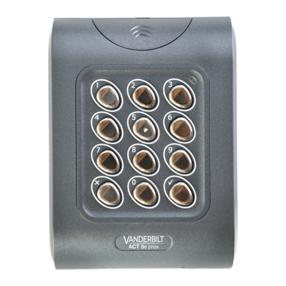
Summary of Contents for Vanderbilt ACT 5e prox
- Page 1 ACT 5e prox Installation and Operating Instructions Document ID: A-100512-e Edition date: 25.06.2019...
- Page 2 Hereby, Vanderbilt International (IRL) Ltd declares that this equipment type is in compliance with the following EU Directives for CE marking: •...
-
Page 3: Table Of Contents
5.9 Check if user has no card assigned 5.10 Program ACT 5e prox options 5.11 Restore factory defaults 6 Wiring and Mounting Diagrams 6.1 ACT 5e prox wiring diagram for strike lock 6.2 ACT 5e prox wiring diagram for mag lock 6.3 Surface mount 6.4 Flush mount 6.5 Flush mount to UK pattress box... -
Page 4: Overview
1.5A @ 30VDC / 1.5A @ 50VAC The ACT 5e prox reader must be powered from a fused AC/DC PSU (12–24V, 1A maximum). If the reader is used in a manner not specified in this document, the protection provided by the reader may be impaired. -
Page 5: Installation Notes
Remember to place the supplied varistor across the terminals of the door strike coil to protect the relay contacts. Do not mount the ACT 5e prox unit near RF sources (e.g. mobile phones, radio transmitters, etc) or metal surfaces. Never use the on-board relay to switch AC mains voltage. An external relay, electrically isolated from the ACT 5e prox, should be used for this purpose. -
Page 6: 30 Second Programming Guide
Enter the details of the Users and their associated codes and card numbers on the User List at the back of this manual. The ACT 5e prox is now ready for normal use. The ACT 5e prox may be returned to its factory default condition at any time by entering the programming mode and pressing three times. -
Page 7: Programming Summary
Set Door Relay Time 5 seconds Add User Card Delete User’s Card Delete Card Number Card or PIN Card and PIN Card and any PIN Permanent Backlight Auto Backlighting Check PIN User Check Card User © Vanderbilt 2019 A-100512-e 25.06.2019... -
Page 8: Act 5E Prox Digital Keypad Programming
Cards may only be assigned to users that do NOT have a card already assigned. When adding cards to the ACT 5e prox, check which users already have cards by using option 81 (see Check if user has no card assigned on page 11). -
Page 9: Change Programming Code
ACT 5e prox – Installation and Operating Instructions ACT 5e prox Digital Keypad Programming Example 1: Assign card 0000200036 to user Example 2: Assign card 0000200036 to user 21 using the keypad Keypad Entry Operation Keypad Entry Operation 9999 Enter programming... -
Page 10: Set Relay Combinations
ACT 5e prox – Installation and Operating Instructions ACT 5e prox Digital Keypad Programming 5.5 Set relay combinations Enter programming mode, then press: Step Keypad Operation Example: Set user 12 to toggle relay when access Entry granted Set Toggle Mode Set Toggle Mode 000 –... -
Page 11: Check If User Has No Card Assigned
5.11 Restore factory defaults Enter the programming code followed by . This restores the ACT 5e prox to its default settings. If the programming code has been forgotten, set it to 9999 as follows: 1. Remove the power from the unit. - Page 12 ACT 5e prox – Installation and Operating Instructions ACT 5e prox Digital Keypad Programming The keypad will not operate correctly without LK1 in place. Defaulting memory takes 3-4 seconds. During this time, the buzzer will sound an elongated tone. © Vanderbilt 2019 A-100512-e 25.06.2019...
-
Page 13: Wiring And Mounting Diagrams
This illustration shows wiring for normally de-energised locks. If normally energised locks are required use the N/C relay contacts. The ACT 5e prox may be powered from 12 or 24V AC or DC. Power up without link if programming code has been lost. -
Page 14: Act 5E Prox Wiring Diagram For Mag Lock
This illustration shows wiring for normally de-energised locks. If normally energised locks are required use the N/C relay contacts. The ACT 5e prox may be powered from 12 or 24V AC or DC. Power up without link if programming code has been lost. -
Page 15: Surface Mount
ACT 5e prox – Installation and Operating Instructions Wiring and Mounting Diagrams 6.3 Surface mount Mount the surface mount collar on the wall using the fixing kit supplied in the box. Place the reader/keypad onto the surface mount collar and clip down into place. -
Page 16: Flush Mount To Uk Pattress Box
ACT 5e prox – Installation and Operating Instructions Wiring and Mounting Diagrams Use the security screw supplied to attached the unit to the flush mount collar. Place the cap onto the unit and push firmly in place. 6.5 Flush mount to UK pattress box Spacers break away from main component when required by installer for use. -
Page 17: User List
7 User List User User Name Card Number Toggle © Vanderbilt 2019 A-100512-e 25.06.2019... - Page 18 ACT 5e prox – Installation and Operating Instructions User List User User Name Card Number Toggle Example: User User Name Card Number Toggle John Smith 0000200036 7529 Download a PDF to record the full user list: http://van.fyi?Link=5eprox_UL © Vanderbilt 2019 A-100512-e 25.06.2019...
- Page 19 © Vanderbilt 2019 Data and design subject to change without notice. Supply subject to availability. Document ID: A-100512-e Edition date: 25.06.2019 Issued by Vanderbilt International Ltd. Clonshaugh Business and Technology Park vanderbiltindustries.com Clonshaugh, Dublin D17 KV 84, Ireland @VanderbiltInd Vanderbilt Industries...


Need help?
Do you have a question about the ACT 5e prox and is the answer not in the manual?
Questions and answers