Table of Contents
Advertisement
Advertisement
Table of Contents

Related Manuals for Leibinger CANVASA Series


Summary of Contents for Leibinger CANVASA Series
- Page 1 CANVASA Original operating manual EN | 2020/02 |...
- Page 2 The compilation is made without any guarantee. Information in this operating manual is subject to change without notice due to ongoing product development. ©2019 LEIBINGER GmbH All rights, including photomechanical reproduction and storage in electronic media, are reserved by LEIBINGER GmbH.
-
Page 3: Table Of Contents
Contents Usage limits ..................... 6 Intended use ....................6 Misuse ......................6 Spatial limits ....................6 Time limits ....................... 7 Other limits ...................... 7 Obligations of the operator ................8 Exclusion of liability ..................9 About this manual ..................10 Function of this document ................ - Page 4 Commissioning ....................27 Switching on the machine Switching the machine off Function test prior to commissioning .............. 27 Checking the safety equipment Operation ....................... 28 The menus..................... 28 Start screen Operation Clock times User management CIP cleaning program CIP sequence Manual operation I Manual operation II Manual operation III (password protected)
- Page 5 Replacement of the drivers: Modification of the filling valve: Faults ......................61 Starting machine after emergency stop ............62 Cleaning ......................63 General cleaning.................... 63 Cleaning product line (CIP) ................65 Cleaning the CO and vacuum nozzles ............68 Cleaning the high-pressure injection nozzles ..........68 Maintenance ....................
-
Page 6: Usage Limits
Only beverage cans that are capable of withstanding the internal pressure generated by the filling process may be used as filling containers. The LEIBINGER filling machine CANVASA II + II must only be used for filling goods that have been explicitly approved by LEIBINGER. -
Page 7: Time Limits
Compliance with the maintenance intervals as per the maintenance plan Compliance with cleaning as per cleaning recommendations and care plan Use of original LEIBINGER spare parts. Wear parts which have to be replaced depending on operating hours or wear are excluded from this... -
Page 8: Obligations Of The Operator
Obligations of the operator The following points must be observed and complied with by the operator: Regular visual inspection of the lines The strict observance of this operating manual Compliance with inspection and maintenance work The operator must check if and which safety components must be replaced after 20 years in order to ensure the continued safety of the machine. -
Page 9: Exclusion Of Liability
The manufacturer is not liable for any resulting damage. Modifications to the LEIBINGER filling machine CANVASA II + II are prohibited. The LEIBINGER filling machine CANVASA II + II must only be used in a technically flawless and operationally reliable condition. Any misuse shall invalidate the manufacturer's warranty, guaran- tee and general liability. -
Page 10: About This Manual
About this manual Important information! This operating manual must be read prior to commissioning. The following points must be observed and complied with: All instructions intended to ensure the safety of the operator and the environment must be observed! ... -
Page 11: Safety Information
Safety information The safety information is designated on the basis of the severity of the danger as follows: Danger! Indicates an immediate hazard involving a high degree of risk that directly results in death or extremely serious injury. Warning! Indicates a hazard involving a moderate degree of risk that results in death or serious injury. Caution! Indicates a hazard involving a low degree of risk that results in minor or moderate injury or material damage. - Page 12 Risk of slipping due to wet floor surfaces The floor around the machine will become wet during operation, which increases the risk of slipping. Risk of poisoning due to harmful gases and vapors! is released during operation of the system. This is why it is necessary to provide suffi- cient room ventilation.
-
Page 13: Information Note
Information note This operating manual contains information notes. Information notes contain important instructions for setting up and operating the machine without any problems. These must be observed without fail. Important information! This information note indicates that failure to comply may result in material or financial dam- age. -
Page 14: Qualification Of Operators / Specialist Personnel / Electricians
Only trained operators, specialist personnel or qualified electricians are permitted to carry out work on the machine. Trained operators Trained operators are those who have been trained by authorized representatives of LEIBINGER GmbH Authorized representatives are fitters and employees of LEIBINGER GmbH. -
Page 15: Qualification For Certain Activities
Qualification for certain activities Qualification Activity Specialist per- Qualified electri- Trained operators sonnel cians ● Operation in set-up mode ● Operation in automatic mode ● Set-up, changing the set-up ● ● ● Troubleshooting ● ● Maintenance ● Work on electrical equipment Work on pneumatic or hydraulic ●... -
Page 16: Markings On The Machine
Markings on the machine Important information! The signs and markings on the housing of the machine and components must not be changed or removed Symbols on the machine Caution, high voltage CE marking Risk of crushing Hot surface Wear eye protection Wear gloves Only lift the machine here 2020-02... -
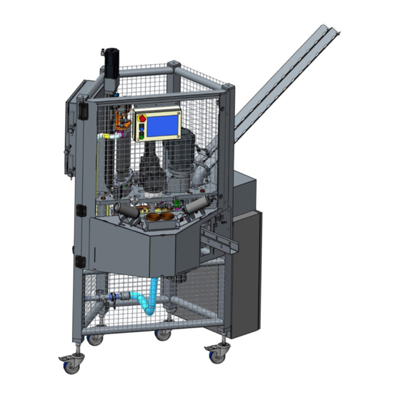
Page 17: Structure And Function
Structure and function Machine overview Fig. 1 Machine overview 1 (1) Valve cabinet (4) Product connec- (7) Can insert tion (2) Rinser (5) Lid slide (8) Can discharge (3) CIP return flow (6) Operating panel (9) Access door 2020-02 CANVASA II + II can filling machine operating manual... - Page 18 Fig. 2 Machine overview 2 (1) Control cabinet (2) Media connections 2020-02 CANVASA II + II can filling machine operating manual...
- Page 19 Fig. 3 Machine overview 3 (1) Can insert (4) High-pressure injection and bubble breaker (2) Pre-gassing (5) Sealer (3) Filling (6) Outlet with can spray 2020-02 CANVASA II + II can filling machine operating manual...
-
Page 20: Production Sequence
Production sequence The can casings are provided on a pallet. The operator fills the lid magazine prior to the start of production. The operator starts the machine. The machine is ready for operation after the home po- sition run and production can start. The operator takes two cans and cleans them on the rinser with the connected medium. -
Page 21: Panel (Control Panel With Controls)
Panel (control panel with controls) Touchscreen Emer- gency Stop Reset Auto Start/Stop Emergency stop switch For immediate stopping of all machine functions in case of emergency. The control unit is switched off. The emergency stop switch must be pulled up again and all axes must be re-referenced before the control unit is switched on again. -
Page 22: Transport
The fork width must be set such as to ensure that the machine is gripped as far out as possible. Transport damages must be immediately reported to the forwarding agent or LEIBINGER. The following points must be observed for intermediate storage: ... -
Page 23: Setting Up The Machine
The following sections of the chapter "Setting up the machine" must, however, be observed, in particular if the machine is not set up and commissioned by LEIBINGER service technicians, e.g. after a change of location. -
Page 24: Connecting The Machine
Connecting the machine Media connections The following connections can be found on the connection panel for the hose connections: Fig. 4 Connection panel Water connection: The can spray and high-pressure injection are supplied via the water connection. Drinking water quality is essential because the water also enters the product via the high-pressure injection. connection: The CO2 connection supplies the pre-gassing, bubble breaker and bottom lid gassing. -
Page 25: Water
Attention! Machine damage due to impure compressed air The machine requires properly conditioned compressed air for operation. All pneumatic equipment is operated with oil-free compressed air unless otherwise indicated. Important information! The following quality classes as per ISO 8573-1 must be adhered to: ... - Page 26 The relevant standards, safety regulations as well as the technical connection conditions of the local utility companies must be observed! If the dosing filling machine is connected to a 230V mains that is separate from the machine, an all-pole isolation switch must be provided in the mains supply line! ...
- Page 27 Commissioning Risk of injury Ensure that nobody is working on the machine and that all protective covers are properly fit- ted before commissioning. Switching on the machine Ensure that the machine is supplied with compressed air, CO2 and water. Switch on the main switch on the control cabinet. ►...
- Page 28 Operation The menus Start screen Manual oper- Operation Settings Logoff ation Operation User interface for automatic operation Settings General settings, product management Manual operation Manual control of all actuators Cleaning program Logoff Log off currently logged in user 2020-02 CANVASA II + II can filling machine operating manual...
- Page 29 Operation Press “Operation” after the start screen appears. The following screen appears: Operation Lid slide full Attention: Water pressure too low Preload pressure: Offset filling end: Sealing process Reset can Emptying ON High-pressure injection counter heating Inlet pressure: Cans per h Can counter Product manage- BACK...
- Page 30 Can counter Can counter that can be reset; only sealed cans are counted Can counter Can counter that cannot be reset; only sealed cans are counted Product management Access to the parameters of the active product Control unit on Switch the control unit on, i.e. off. Messages Displays pending messages Clock times...
- Page 31 Filling process Shows the duration of the filling process. Sealing process Shows the duration of the sealing process. Rotary table Shows the duration of the rotary table movement. Total Adds the duration of the rotary table movement to the duration of the slower of the filling and sealing processes to calculate the total cycle time and the projected output per hour.
- Page 32 CIP cleaning program Operation Input pressure: Clean/flush CO2 units Runtime: Remaining time: Stop Start Control unit off BACK Menu Messages Inlet pressure Displays the pressure at the product infeed CIP Start Starts the first CIP run with the specified runtime CIP Stop Interrupts the current CIP run regardless of the remain- ing time.
- Page 33 CIP sequence Start CIP Insert rinsing bottle mes- Start further CIP run sage Please insert rinsing bottle and Rotary axis clocking acknowledge Sealing 1 + 2 in S position Switch on CIP system message Rinsing bottles are clocked out Filling axis to cleaning position Drive traverses Time elapsed or CIP Stop CIP ended...
- Page 34 Manual operation I Switch on machine Select manual operation after the start screen appears Manual operation Open filling axis Vacuum Filling valve 1 Filling valve 2 Fill axis jog + reference side open open Start filling pro- Trigger OP1 + Sealing on Blow (5 s) Filling axis jog -...
- Page 35 Lid carriage Forward/backward stroke of the lid carriage Rotary table jog + Clockwise movement of the rotary star wheel Set rotary table zero point Defines the current position as the new zero point 00000° Display of the current rotary star wheel position Extend rotary plate Forward/backward stroke of the rotary plate on the sealer...
- Page 36 Manual operation II Manual operation (10s) CO2 pre- (10 s) Bottom lid Bubble breaker High-pressure in- Blow off chuck gassing gassing jection Can spray Can feed Rinser cylinder Rinser water Blow-off cans Can turner Can barrier Printer BACK Menu High-pressure injection Forward/backward stroke of the high-pressure injection nozzles CO2 pre-gassing...
- Page 37 Can feed Actuates the feed pusher of the automatic can feed (op- tional) Rinser cylinder Actuates the rinser cylinder of the automatic can feed (optional) Rinser water Actuates the rinsing valve of the automatic can feed (op- tional) Can turner Actuates the slew drive of the automatic can feed (op- tional) Can barrier...
- Page 38 Product management I Product management Product: Can type: Filling speed: Filling acceleration: Begin bubble breaker: Bubble breaker duration: Begin high-pressure in- jection: High-pressure injection duration: Save parame- Next page BACK Operation Menu ters + / - Product selection 00 0000000000000000 Display of the active product Can type Selection of can type from the library...
- Page 39 Product management II Product management Product: Rotary table speed: Rotary table acceleration: Rotary table deceleration: Relief stroke: Relief speed: Relief acceleration: Relief deceleration: Save parame- Next page BACK Operation Menu ters + / - Product selection 00 0000000000000000 Display of the active product Rotary table speed Setting of the rotary table speed Rotary table acceleration...
- Page 40 Product management III Parameters (e.g. reference position, pressure, etc.) are displayed in the fields with a white back- ground. These parameters can be modified Product management Product: Begin pre-gassing: Rotary plate deceleration: Rinsing time: Maximum downtime: Copy param- eters Save parame- Menu BACK Next page...
- Page 41 Settings Menu Date/time Language Product management User manage- BACK Menu ment Date / time Date and time setting options Language Selects the language of the user interface Product management Access to product-specific parameters 2020-02 CANVASA II + II can filling machine operating manual...
- Page 42 Language Language Login BACK Start screen Menu German Logout Language Select language Login / Logout User log in/out Start screen Back to the start screen 2020-02 CANVASA II + II can filling machine operating manual...
- Page 43 System Time Hours: Year: Month: Minutes: Seconds: Day: Current time: Set time BACK Cleaning screen Menu Touch calibri. Year, month etc. Manual input of date and time Current time Display of the currently set system time Set time Saves the newly input system time Old messages Old messages Pending mes-...
- Page 44 Pending messages Pending messages BACK Old messages Menu Old messages Displays old messages Should the operator be required to intervene during operation of the system, an operation mes- sage is shown on the display. This message contains instructions on what to do next. 2020-02 CANVASA II + II can filling machine operating manual...
- Page 45 Automatic operation sequence Clock sequence Rinsing sequence Insert cans Rinsing ac- tive Release of Both cans on all stations ring unit End rinsing Rinsing in progress Drive clocks Can re- moved Drive position reached Release at stations Filling sequence Lid separation sequence Cans clock in sta- Release of the tion...
- Page 46 Can present Lid carriage in H position Rotary plate in S position Rotary plate does not come to A po- sition OP 1 + 2 in S position OP 1 + 2 in S position Rotary plate in G position Rotary plate in H position Rotary plate in S position OP 1 + 2 not in S position...
- Page 47 Fault messages Alarm Remedy No compressed air present Connect compressed air to the sys- Protective flap open Close protective door Supply 24V triggered collective mes- Check fuse Contact service depart- sage ment Emergency-stop relay switched off Reset emergency stop with the re- Acknowledge emergency-stop set button Emergency-stop operating panel actu-...
- Page 48 Filling valve 1 not in H POS Set the sensor Filling valve 1 not in S POS Set the sensor Filling valve 2 not in H POS Set the sensor Filling valve 2 not in S POS Set the sensor Lid carriage not in H pos Set the sensor Lid carriage not in S pos...
- Page 49 Product management Product: Can type: Preload pressure: Relative Offset filling end: Filling speed: Filling acceleration: Begin bubble breaker: Bubble breaker duration: Begin high-pressure injection: High-pressure injection duration: Save parame- Operation BACK Menu Next screen ters Fig. 5 Product parameters The following sequence is recommended for adjusting the parameters: Parameterization of the filling process until a quick, foam-free or low-foam filling is en- sured and the desired filling quantity is reached.
- Page 50 Filling process parameterization: Four parameters are essential for the filling process: Input pressure (set via tank pressure); experience indicates 1.3 to 1.6 bar Preload pressure; experience indicates a relative pressure (pressure difference) of 0.3-0.4 bar. Filling speed; experience indicates that a slow initial speed (e.g. 40mm/s) is recommended, which can then be increased gradually.
- Page 51 Intensity, i.e. flow rate; can be adjusted via a needle shut-off valve on the rear side of the ma- chine The following foaming behavior can be achieved by adjusting these settings: High-pressure injection takes place directly before the rotary table is cycled forwards. ...
- Page 52 Intensity, i.e. how much is blown; can be adjusted via flow regulator The following should be achieved by adjusting these settings: All large bubbles are blown down from the foam crown. As large a foam crown as possible remains. Fig.
- Page 53 Fig. 10 Flow regulator for bubble breaker, pre- and bottom lid gassing 2020-02 CANVASA II + II can filling machine operating manual...
- Page 54 Rinsing cans The cans can be rinsed or blown out before being deposited in the machine (depending on con- nected media; see 8.1). The cans are held manually into the prisms in this case. When both cans are in position, the respective valve opens for one second. We recommend turning the cans, es- pecially when rinsing with water.
- Page 55 Incorrect can guide parts can lead to severe machine damage for which LEIBINGER GmbH shall assume no liability. Retrofitting to other can heights There are two corresponding spacers for each type of can, which are fitted under the running plate so that a constant height of the can top edge over all types is guaranteed.
- Page 56 The only exception is the 500ml standard can, for which no spacer is required. Fig. 13 Running plate without spacers (for 500ml standard can) For removing or inserting the spacers, the rotary star wheel can be raised by turning the hand- wheel (2) after loosening the clamping screw on the adjusting ring (1) and the rotary plate.
- Page 57 In addition, spacers matching the can height must be put on the rotary plates for the sealing unit. The only exception is the 500-ml standard can for which no spacer is required. Fig. 15 Spacers for rotary plates Fig. 16 Rotary plates 2020-02 CANVASA II + II can filling machine operating manual...
- Page 58 Retrofitting to other can diameters (optional) Sleek cans can also be filled with the machine if the convertible filling valve is installed. This does, however, require advanced retrofitting: Retrofitting to other can heights (see 11.1) Adjustment of the bypass ...
-
Page 59: Replacement Of The Drivers
Replacement of the drivers: Since the diameter of the sleek can is smaller than that of the standard can, the corresponding drivers (6x) must be used in each case. These can be removed by loosening two screws in each case. Fig. - Page 60 Since this outer diameter must be sealed accordingly, the two centering bells (1) are also re- placed by loosening two screws (2) each. Fig. 21 Centering bells INFO: The valve must only be modified provided that no drivers are fitted, since only then is the required space available.
-
Page 61: Faults
Faults Fault Possible cause Remedy Main switch not switched on Switch on main switch Machine cannot be switched on Fuse defective Notify specialist, replace fuse Product is discontin- Seals damaged or obsolete Replace seals No air pressure pre- Supply line defect Check supply line and repair sent if necessary... -
Page 62: Starting Machine After Emergency Stop
Fault Possible cause Remedy Motor overloaded Motor defective Ventilation openings contaminated Clean openings Faults occur when the Bottom lid gassing displaced Realignment via adjusting lid is fed in ring Unusually strong vi- Incorrect rotary star wheel position. Manually bring the rotary star brations occur during wheel into the ideal position sealing... -
Page 63: Cleaning
The information provided here for cleaning the machine are recommendations from LEIBINGER GmbH. LEIBINGER GmbH is not liable for any damage caused by unsuitable cleaning agents. All values specified, such as intervals, may vary depending on the machine and the customer's system (CIP system). - Page 64 Cleaning agents that contain chlorine cause considerable damage to plastic parts such as centering bells or shut-off valves made of plastic. LEIBINGER shall assume no liability for damage caused by the use of cleaning agents that contain chlorine. Caution! Material damage The following components must not be hosed down with water: ...
-
Page 65: Cleaning Product Line (Cip)
Do not use cleaning agents containing chlorine! Cleaning agents that contain chlorine cause considerable damage to plastic parts. LEIBINGER shall assume no liability for damage caused by the use of cleaning agents that contain chlorine. Refer also to the general instructions for cleaning! - Page 66 A special program is available for cleaning: Connect the CIP system to the product infeed of the machine. Connect the CIP return flow to the machine. Enter the desired duration for the first rinse cycle with water. Press “CIP Start” Follow the step-by-step instructions displayed on the screen.
- Page 67 Fig. 24 Area to be manually cleaned Fig. 25 Rinsing bottles for different can formats 2020-02 CANVASA II + II can filling machine operating manual...
-
Page 68: Cleaning The Co And Vacuum Nozzles
Cleaning the CO and vacuum nozzles Several nozzles are installed on the machine: Pre-gassing Bubble breaker Bottom lid gassing Vacuum These can be connected to the water connection and flushed via four 3-way ball valves below the valve cabinet. -
Page 69: Maintenance
Maintenance Important information! The maintenance intervals must be adhered to so that the functional and operational safety of the machine is preserved. All work on the electrical system must only be carried out by specialist personnel complying with the safety requirements of EN 50110-1. The legal regulations relating to the documentation of maintenance work must be complied with. -
Page 70: Disconnect The Machine From The Electrical Supply Network
Disconnect the machine from the electrical supply network Switch off and lock the main switch or attach an appropriate warning sign. HAUPTSCHALTER MAIN SWITCH OPEN IN OPEN IN 0 POSITION OFF POSITION Fig. 27 Main switch switched off and secured against reactivation Disconnect the machine from the compressed air supply The compressed air supply is connected to the machine via a quick coupling. -
Page 71: Lubrication
The following points must be observed when lubricating and greasing to avoid material dam- age: Only use the food grade lubricant prescribed by LEIBINGER (NSF H1). The lubrication intervals relate to single shift operation (8 hours/day). Filling valve lubrication points The sealing surface of the filling tube must be lightly greased before each use in order to lubricate the rod seals. -
Page 72: Spindle Axis Lubrication Points
Spindle axis lubrication points Fig. 29_2 Spindle axis lubrication points = Ball screw lubrication bore: 2.5 g lubricant quantity per lubrication = Guide lubrication bores: 0.8 g lubricant quantity per lubrication See the included original FESTO operating manual! 2020-02 CANVASA II + II can filling machine operating manual... -
Page 73: Care
Care Safety Warning! Risk of injury Switch off the machine prior to starting work and secure it against reconnection. Warning! Risk of injury Ensure that nobody is working on the machine and that all protective covers are properly fit- ted before switching the machine on. Caution! Material damage The machine must only be put into operation again after it has been inspected by the cus- tomer service department if liquid penetrated into the electrical components of the machine. -
Page 74: Maintenance Plan
Maintenance plan Work to be carried out External cleaning Clean product lines Grease sealing rollers Grease filling valve Check positioning of rotary star wheel Check sealing strokes Checking the safety functions Check emergency-stop button function Check function of safety hinge Leakage checks on the pneumatic compo- nents Testing according to DGUV Regulation 3... -
Page 75: Daily Maintenance (Every 8 Operating Hours)
Daily maintenance (every 8 operating hours) Cleaning of the complete machine. Removal of all fragments and other impurities. Visual inspection of the control panel. Immediately replace damaged or non-functional ele- ments. Flushing the media-carrying components. Visual inspection of all contact rubbers on the filling valves for intactness. Immediately re- place defective sealing rubbers. - Page 76 Fig. 30 Filter plate on fan (example) Replace filter plate on the fan if it is black-gray. INFO: We highly recommend concluding a maintenance contract with LEIBINGER customer service 2020-02 CANVASA II + II can filling machine operating manual...
-
Page 77: Setting The Sealing Strokes
Setting the sealing strokes The stroke of the sealing rollers is set via stop nuts in the rear area. It is important to note that the sealer for OP1 moves to the center of the machine and to OP2 from the center. These move- ments can be performed individually in manual mode. - Page 78 Fig. 31 Manual operation menu Fig. 32 Fold width after OP1 Fig. 33 Fold width after OP2 2020-02 CANVASA II + II can filling machine operating manual...
-
Page 79: Setting Rotary Star Wheel Position
Fig. 34 Stop nuts for OP1 (right) and OP2 (left) Setting rotary star wheel position The zero point of the rotary star wheel can be approached and set again in the "Manual opera- tion" menu if required. This must be selected so that both cans can rotate freely in the sealing unit. -
Page 80: Adjusting Bottom Lid Gassing
Adjusting bottom lid gassing The bottom lid gassing can be adjusted via the adjusting ring on the holder. Fig. 36 Bottom lid gassing holder 2020-02 CANVASA II + II can filling machine operating manual... -
Page 81: Resetting The Heater Temperature Limiter
Resetting the heater temperature limiter The temperature of the high-pressure injection heating is monitored by two sensors. One is con- nected to the thermostat that regulates the heat output. The other serves as additional protection against overheating. If this overheats, the limiter switches off the heater to prevent any damage. After the system has cooled down, this limiter must be reset manually using the green switch in- side the heating system. -
Page 82: Technical Data
Technical data General data Measurement Value Nominal capacity Up to 1200 cans/h (330 ml) Connection values 230 V; 50Hz Ambient conditions Transport/storage: - Temperature -20 to +50 °C - Relative air humidity 30 to 75% without condensation - Air pressure 500 to 1060 hPa ... -
Page 83: Annex
The machine and accessories must be disposed of at the end of their service life pursuant to the applicable local laws. This applies especially to waste oil, used grease and other chemical substances. Please contact LEIBINGER GmbH in case of any questions. Machine parts and operating resources must not be disposed of with household waste. 2020-02...
Need help?
Do you have a question about the CANVASA Series and is the answer not in the manual?
Questions and answers