Advertisement
Available languages
Available languages
Quick Links
www.elektra.eu
CACM25 - PROi
Connection kit for cold applied
UK
installation with M25 gland
Zestaw przyłączeniowy do montażu
PL
na zimno z wpustem M25
êîìïëåêò äëÿ ñîåäèíåíèÿ
RU
ñ õîëîäíûì êàáåëåì ñ ïàçîì M25
DE
Anschlussset mit M25 Kabeleinführung
Advertisement

Subscribe to Our Youtube Channel
Related Manuals for ELEKTRA CACM25-PROi


Summary of Contents for ELEKTRA CACM25-PROi
- Page 1 CACM25 - PROi Connection kit for cold applied installation with M25 gland Zestaw przyłączeniowy do montażu na zimno z wpustem M25 êîìïëåêò äëÿ ñîåäèíåíèÿ ñ õîëîäíûì êàáåëåì ñ ïàçîì M25 Anschlussset mit M25 Kabeleinführung...
- Page 2 CACM25-PROi...
- Page 3 CACM25-PROi Directive ATEX 2014/34/EU ATEX KBD 19ATEX0003U II 2G Ex eb IIC Gb II 2D Ex tb IIIC Db IECEx KDB 19.0001U Ex eb IIC Gb Ex tb IIIC Db Standards EN 60079-0, EN 60079-7, EN 60079-30-1 Operating temperature range £...
- Page 4 CACM25-PROi Note: Electrical systems must be checked before the first start-up. Anti-frost systems must be checked before each heating season. Regularly check systems for maintaining process temperature, min. twice a year. Note: The design of electrical heating systems must be executed according to the design directives for explosive conditions, basing on the manufacturer’s recommendations...
-
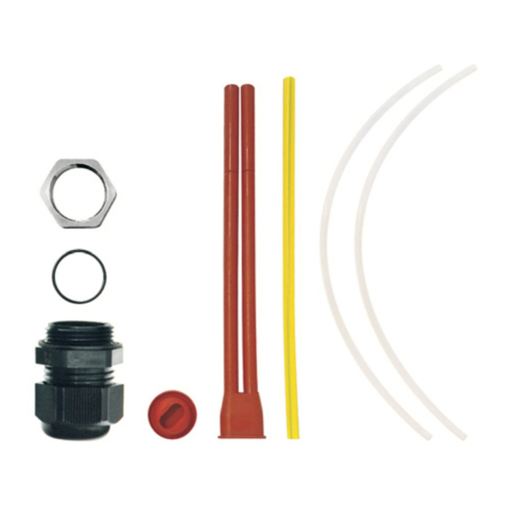
Page 5: Kit Contents
Kit contents: M25 gland and gasket with oval opening double insulation silicone tubes, 150mm long auxiliary insulation tubes covering silicone tubes, 180mm long green-yellow tube, 160mm long Note: Installation must be executed in a clean and dry place. Protect the termination points of the heating cable, as well as all the components of the installation kit, against moisture, both before and during... - Page 6 CACM25-PROi List of installation tools not included in the kit: snap-off blade utility knife flat-head screwdriver adjustable wrench or 28mm open-end wrench and 32mm open-end wrench side cutter...
- Page 7 The construction of heating cables: outer sheath protective screen, copper wire braid electrical insulation self-regulating heating element conductor wire The installation kit is recommended for the following cables: ® SelfTec PROi LT / F 10 ® SelfTec PROi LT / F 20 ®...
- Page 8 CACM25-PROi ³300mm Place the gland with the oval opening gasket on the heating cable, following the sequence shown in the picture, in the distance of min. 300mm from the beginning of the cable. Split the cable sheath delicately along the length...
- Page 9 Remove the sheath. Insert the heating element through the opening in the protective screen.
- Page 10 CACM25-PROi Twist the screen. 140mm Split and strip the insulation along the length of 140mm.
- Page 11 Note: The splits should be made so that the conductor wires are not damaged with the blade of the utility knife or the side cutter. Split the heating element open revealing the conductor wires along the length of 140mm.
- Page 12 CACM25-PROi Pull on the 180mm-long auxiliary insulation tubes covering silicone tubes, as well as the 150mm-long double silicone insulation tubes. Note: Pull the auxiliary tubes on so that the conductor wires remain twisted.
- Page 13 Pull the common part of the double silicone tubes onto the earlier uncovered electric insulation of the heating cable, along the length of 20mm. Note: Rotation might cause the short circuit of the conductor wires.
- Page 14 CACM25-PROi Put the green-yellow 160mm-long tube onto the twisted protection screen. Pull out the auxiliary tubes covering the 180mm- long tubes and save them in case any modification of the heating circuit becomes necessary.
- Page 15 12mm 12mm max. 40mm Align the conductor wires and twisted protective screen, leaving the wires isolated along the length of 12mm. If necessary, shorten the silicone insulation tubes by a max. 40 mm. Enter the prepared heating circuit, together with the components recreating insulation, into the electrical box through the counter nut so that the heating cable’s sheath is inserted into the box along the length of 10mm.
- Page 16 CACM25-PROi 12mm 12mm...
- Page 17 ST terminal blocks positioned on the installation rail of the power supply electrical box enable connecting the conductor wires of the heating cables, as well as the wires of the installation cables, as above.
- Page 18 CACM25-PROi...
- Page 19 CACM25 - PROi Connection kit for cold applied installation with M25 gland Zestaw przyłączeniowy do montażu na zimno z wpustem M25 êîìïëåêò äëÿ ñîåäèíåíèÿ ñ õîëîäíûì êàáåëåì ñ ïàçîì M25 Anschlussset mit M25 Kabeleinführung...
- Page 20 CACM25-PROi...
- Page 21 CACM25-PROi Dyrektywa ATEX 2014/34/EU ATEX KBD 19ATEX0003U II 2G Ex eb IIC Gb II 2D Ex tb IIIC Db IECEx KDB 19.0001U Ex eb IIC Gb Ex tb IIIC Db Standard EN 60079-0, EN 60079-7, EN 60079-30-1 Zakres temperatury pracy £...
- Page 22 CACM25-PROi Uwaga: Instalacja elektryczna powinna zostać sprawdzona przed pierwszym uruchomie- niem. Instalacja zabezpieczająca przed zamarza- niem powinna zostać sprawdzona przed rozpoczęciem okresu grzewczego. Instalację utrzymania temperatury proceso- wej należy sprawdzać w regularnych odstępach czasu - przynajmniej dwa razy w roku.
- Page 23 Zestaw zawiera: dławik M25 i uszczelka z owalnym otworem podwójne rurki silikonowe, izolacyjne o długości 150mm rurki pomocnicze osłaniające rurki silikonowe, izolacyjne o długości 180mm rurkę zielono-żółtą o długości 160mm Uwaga: Montaż należy wykonać w miejscu czystym i suchym. Końce przewodu grzejnego i elementy zestawu montażowego przed i w trakcie instalacji należy zabezpieczyć...
- Page 24 CACM25-PROi Zestawienie narzędzi montażowych niewchodzących w skład zestawu: nóż monterski z ostrzem łamanym śrubokręt płaski klucz nastawny lub klucz płaski 28mm i klucz płaski 32mm obcinacz z ostrzem bocznym...
- Page 25 Konstrukcja przewodów grzejnych: powłoka zewnętrzna ekran ochronny, oplot z drutów miedzianych izolacja elektryczna samoregulujący element grzejny żyła zasilająca Zestaw przeznaczony do przewodów: ® SelfTec PROi LT / F 10 ® SelfTec PROi LT / F 20 ® SelfTec PROi LT / F 33 ®...
- Page 26 CACM25-PROi ³300mm Umieścić dławik z uszczelką z otworem owalnym na przewodzie grzewczym w kolejności zgodnej z rysunkiem, w odległości co najmniej 300mm od początku przewodu. Na długości 170mm rozciąć delikatnie powłokę przewodu w taki sposób żeby nie uszkodzić ekranu ochronnego.
- Page 27 Zdjąć powłokę. Przez otwór w ekranie ochronnym wysunąć element grzejny.
- Page 28 CACM25-PROi Skręcić ekran. 140mm Naciąć i zdjąć izolację na długości 140mm.
- Page 29 Uwaga: Nacięcia należy wykonać w taki sposób, aby nie uszkodzić żył zasilających ostrzem noża monterskiego lub obcinaczem z ostrzem bocznym. Rozciąć element grzejny odsłaniając żyły zasilające na długości 140mm.
- Page 30 CACM25-PROi Nasunąć rurki pomocnicze osłaniające rurki silikonowe, izolacyjne o długości 180mm oraz podwójne rurki silikonowe, izolacyjne o długości 150mm. Uwaga: Rurki pomocnicze należy nasuwać w taki sposób żeby nie doprowadzić do rozplece- nia żył zasilających.
- Page 31 Część wspólną, podwójnych rurek silikonowych, nasunąć na odsłoniętą wcześniej izolację elektryczną przewodu grzejnego na długość 20mm. Uwaga: Obrócenie może spowodować zwarcie żył zasilających.
- Page 32 CACM25-PROi Rurkę zielono-żółtą o długości 160mm założyć na skręcony ekran ochronny. Wysunąć rurki pomocnicze osłaniające rurki o długości 180mm i zachować na wypadek modyfikacji obwodu grzejnego.
- Page 33 12mm 12mm maks. 40mm Wyrównać żyły zasilające i skręcony ekran ochronny pozostawiając odizolowane żyły długości 12mm. Jeżeli zachodzi taka potrzeba, skrócić izolacyjne rurki silikonowe maksymalnie o 40 mm. Wprowadzić przygotowany obwód grzejny z elementami odtwarzającymi izolację do puszki przez przeciwnakrętkę tak, aby powłoka przewodu grzejnego wchodziła do puszki na długości 10mm.
- Page 34 CACM25-PROi 12mm 12mm...
- Page 35 Zaciski typu ST umieszczone na szynie montażowej puszki zasilającej pozwalają na łączenie żył zasilających przewodów grzejnych oraz żył przewodów instalacyjnych w następujący sposób.
- Page 36 CACM25-PROi...
- Page 37 CACM25 - PROi Connection kit for cold applied installation with M25 gland Zestaw przyłączeniowy do montażu na zimno z wpustem M25 êîìïëåêò äëÿ ñîåäèíåíèÿ ñ õîëîäíûì êàáåëåì ñ ïàçîì M25 Anschlussset mit M25 Kabeleinführung...
- Page 38 CACM25-PROi...
- Page 39 CACM25-PROi Äèðåêòèâà ATEX 2014/34/EU ATEX KBD 19ATEX0003U II 2G Ex eb IIC Gb II 2D Ex tb IIIC Db IECEx KDB 19.0001 Ex eb IIC Gb Ex tb IIIC Db Ñòàíäàðò EN 60079-0 EN 60079-7 EN 60079-30-1 Äèàïàçîí ðàáî÷èõ òåìïåðàòóð...
- Page 40 CACM25-PROi Âíèìàíèå! Ïåðåä ïåðâûì ïóñêîì ñèñòåìû îáîãðåâà ïðîâåðüòå âñå ýëåêòðè÷åñêèå ïîäêëþ÷åíèÿ. Ñèñòåìû çàùèòû îò çàìåðçàíèÿ íåîáõîäè ìî ïðîâåðÿòü ïåðåä íà÷àëîì ñåçîíà îáîãðåâà. Ìû ðåêîìåíäóåì ïðîâåðÿòü ñïîñîáíîñòü ñèñòåìû ïîääåðæèâàòü çàäàííóþ òåìïåðà òóðó â ïðîöåññå ðàáîòû ìèíèìóì 2 ðàçà â ãîä. Âíèìàíèå! Ïðîåêòíàÿ...
- Page 41 Â êîìïëåêò âõîäèò: ââîä Ì25 ñ óïëîòíèòåëåì (ñ îâàëüíûì îòâåðñòèåì) cäâîåííàÿ ñèëèêîíîâàÿ èçîëèðóþùàÿ òðóáêà äëèíîé 150ìì âñïîìîãàòåëüíûå òðóáêè ñ ñèëèêîíîâûì ïîêðûòèåì äëÿ èçîëÿöèè æèë, 2 øò., 180ìì æåëòî-çåëåíàÿ òðóáêà äëÿ çàçåìëÿþùåé æèëû, äëèíà 160ìì Âíèìàíèå! Ìîíòàæ äîëæåí îñóùåñòâëÿòüñÿ â ñóõîì è...
- Page 42 CACM25-PROi Ïðè ìîíòàæå ïîòðåáóþòñÿ ñëåäóþùèå èíñòðóìåíòû è ïðèñïîñîáëåíèÿ (íå âõîäÿò â êîìïëåêò ïîñòàâêè) : âûäâèæíîé íîæ äëÿ ðàçäåëêè êàáåëÿ ïëîñêàÿ îòâåðòêà ðàçâîäíîé êëþ÷ èëè ðîæêîâûå êëþ÷è íà 28ìì è 32ìì áîêîðåçû...
- Page 43 Êîíñòðóêöèÿ íàãðåâàòåëüíîãî êàáåëÿ: íàðóæíàÿ îáîëî÷êà ýêðàíèðóþùàÿ îïëåòêà èç ìåäíîé ïðîâîëîêè èçîëÿöèÿ ñàìîðåãóëèðóþùàÿñÿ ìàòðèöà òîêîïðîâîäÿùèå æèëû Êîìïëåêò ðåêîìåíäóåòñÿ äëÿ èñïîëüçîâàíèÿ ñî ñëåäóþùèìè êàáåëÿìè: ® SelfTec PROi LT / F 10 ® SelfTec PROi LT / F 20 ® SelfTec PROi LT / F 33 ®...
- Page 44 CACM25-PROi ³300 ìì Óñòàíîâèòå ââîä ñ óïëîòíèòåëåì â ïîðÿäêå, óêàçàííîì íà êàðòèíêå, íà ðàññòîÿíèè íå ìåíåå 300ìì îò íà÷àëà/êðàÿ êàáåëÿ. Àêêóðàòíî, íå ïîâðåäèâ ýêðàíèðóþùóþ îïëåòêó, ñäåëàéòå íàäðåç íàðóæíîé îáîëî÷êè íàãðåâàòåëüíîãî êàáåëÿ äëèíîé 170 ìì.
- Page 45 Ñíèìèòå íàðóæíóþ îáîëî÷êó. ×åðåç îòâåðñòèå â çàùèòíîì ýêðàíå àêêóðàòíî èçâëåêèòå íàãðåâàòåëüíûé ýëåìåíò (ìàòðèöó).
- Page 46 CACM25-PROi Ñêðóòèòå ýêðàíèðóþùóþ îïëåòêó â æãóò. 140 ìì Ñäåëàéòå íàäðåç èçîëÿöèè ìàòðèöû äëèíîé 140ìì è ñíèìèòå åå.
- Page 47 Âíèìàíèå! Íàäðåçû áîêîðåçàìè èëè íîæîì íåîáõîäèìî äåëàòü òàê, ÷òîáû èçáåæàòü ïîâðåæäåíèÿ òîêîïðîâîäÿùèõ æèë. Èçâëåêèòå òîêîïðîâîäÿùèå æèëû èç ìàòðèöû íà äëèíó 140ìì.
- Page 48 CACM25-PROi Íàäåíüòå íà æèëû âñïîìîãàòåëüíûå èçîëèðó- þùèå òðóáêè ñ ñèëèêîíîâûì ïîêðûòèåì äëèíîé 180ìì, à çàòåì ñäâîåííóþ ñèëèêîíîâóþ òðóáêó äëèíîé 150ìì. Âíèìàíèå! Ñëåäèòå, ÷òîáû ïðè óñòàíîâêå äîïîëíè- òåëüíûõ òðóáîê ïðîâîëîêè òîêîïðîâîäÿ- ùèõ æèë îñòàâàëèñü ñêðó÷åííûìè.
- Page 49 Çàäâèíüòå îáùåå îñíîâàíèå ñäâîåííîé ñèëèêîíî- âîé òðóáêè íà çà÷èùåííûé ó÷àñòîê äëèíîé 20ìì. Âíèìàíèå! Ïåðåêðó÷èâàíèå æèë ìîæåò ïðèâåñòè ê êîðîòêîìó çàìûêàíèþ.
- Page 50 CACM25-PROi Óñòàíîâèòå æåëòî-çåëåíóþ òðóáêó äëèíîé 160ìì íà ñêðó÷åííóþ â æãóò ýêðàíèðóþùóþ îïëåòêó. Èçëåêèòå âñïîìîãàòåëüíûå òðóáêè äëèíîé 180ìì èç ñäâîåííîé òðóáêè è ñîõðàíèòå èõ íà ñëó÷àé, åñëè ïîòðåáóåòñÿ âíåñòè èçìåíåíèÿ â ñîåäèíåíèå.
- Page 51 12 ìì 12 ìì ì ê a c. 40 ìì Îñòàâüòå ñâîáîäíûìè / íåèçîëèðîâàííûìè ïî 12ìì íà òîêîïðîâîäÿùèõ æèëàõ è æèëå çàçåìëåíèÿ. Ïðè íåîáõîäèìîñòè óêîðîòèòå ñèëèêîíîâûå èçîëÿöèîííûå òðóáêè ìàêñèìóì 40 ìì. Ââåäèòå ïîäãîòîâëåííûé êîíòóð îáîãðåâà ñî âñåìè êîìïîíåíòàìè èçîëÿöèè â êîðîáêó òàê, ÷òîáû...
- Page 52 CACM25-PROi 12 ìì 12 ìì...
- Page 53 Êëåììíûå áëîêè , íàõîäÿùèåñÿ â ðàñïðåäåëèòåëüíîé êîðîáêå, îáåñïå÷èâàþò ïîäêëþ÷åíèå æèë íàãðåâàòåëüíîãî êàáåëÿ è êàáåëåé ïèòàíèÿ ñïîñîáîì, óêàçàííûì íà êàðòèíêå íèæå.
- Page 54 CACM25-PROi...
- Page 55 CACM25 - PROi Connection kit for cold applied installation with M25 gland Zestaw przyłączeniowy do montażu na zimno z wpustem M25 êîìïëåêò äëÿ ñîåäèíåíèÿ ñ õîëîäíûì êàáåëåì ñ ïàçîì M25 Anschlussset mit M25 Kabeleinführung...
- Page 56 CACM25-PROi...
- Page 57 CACM25-PROi Direktive ATEX 2014/34/EU ATEX KBD 19ATEX0003U II 2G Ex eb IIC Gb II 2D Ex tb IIIC Db IECEx KDB 19.0001U Ex eb IIC Gb Ex tb IIIC Db Normen EN 60079-0, EN 60079-7, EN 60079-30-1 Betriebstemperaturbereich £ £ £...
- Page 58 CACM25-PROi Achtung: Elektrische Systeme müssen vor dem ersten Start geprüft werden. Frostschutzsysteme müssen vor dem Beginn der nächsten Heizperiode geprüft werden. Prüfen Sie die Betriebstemperatur der Systeme regelmäßig mindestens zweimal pro Jahr. Achtung: Die Konstruktion elektrischer Heizsysteme muss gemäß den Konstruktionsanweisungen für explosive Bedingungen, basierend auf...
- Page 59 Das Set beinhaltet: drossel M25 mit ovaler Dichtung Doppeltes Isolationssilikonrohr mit der Länge von 150mm Isolierrohre zum Abschirmen der Silikonrohre mit der Länge von 180mm grün-gelbes Rohr mit der Länge von 160mm Achtung: Die Montage muss an einem sauberen und trockenen Ort durchgeführt werden. Die Endungen der Heizkabel und Elemente des Montagesatzes sollten vor und während der Installation vor Feuchtigkeit geschützt...
- Page 60 CACM25-PROi Liste der im Montagesatz nicht enthaltenen Werkzeuge: Cutter-Messer flacher Schraubendreher Universalschlüssel oder Schraubenschlüssel 28mm und Schraubenschlüssel 32mm Seitenschneiderzange...
- Page 61 Aufbau der Heizkabel: Kabelmantel Schutzschirm, Kupferdrahtbeflechtung elektrische Isolation selbstregulierendes Heizelement Leiterdraht Zur Verwendung mit folgenden Kabel bestimmt: ® SelfTec PROi LT / F 10 ® SelfTec PROi LT / F 20 ® SelfTec PROi LT / F 33 ® SelfTec PROi MT / F 30 ®...
- Page 62 CACM25-PROi ³300mm Die Stopfbuchse mit der ovalen Öffnung auf dem Heizkabel in der in der Zeichnung angegebenen Reihenfolge mit einem Abstand von mindestens 300mm zum Anfangspunkt des Heizkabels anbringen. Den Kabelmantel auf einer Länge von 170mm vorsichtig aufschneiden ohne dabei...
- Page 63 Den Mantel abnehmen. Durch die Öffnung im Schutzschirm das Heizelement hinausschieben.
- Page 64 CACM25-PROi Den Schutzschirm zusammendrehen. 140mm Die Isolierung auf der Länge von 140mm anschneiden und abnehmen.
- Page 65 Achtung: Die Schnitte so durchführen, dass die Leiterdrähte nicht durch das Cutter-Messer oder den Seitenschneider beschädigt werden. Das Heizelement spalten, sodass die Leiterdrähte auf einer Länge von 140mm abgezogen werden können.
- Page 66 CACM25-PROi Die 180mm langen Isolierrohre zum Abschirmen der Silikonrohre als auch die 150mm langen doppelten Silikonrohre vorsichtig auf die Leiterdrähte ziehen. Achtung: Die Isolierrohre so auf die Leiterdrähte schieben, dass sich die Enden der Leiterdrähte nicht auflösen.
- Page 67 Den gemeinsamen Teil der Doppelsilikonrohre auf einer Länge von 20mm auf die vorher aufgedeckte elektrische Isolierung des Heizabels ziehen. Achtung: Das Verdrehen der Leiterdrähte kann einen Kurzschluss verursachen.
- Page 68 CACM25-PROi Das grün-gelbe Rohr mit der Länge 160mm auf den Schutzschirm aufziehen. Die Isolierrohre mit der Länge 180mm herausziehen und für den Fall einer Modifizierung der Heizkabel verwahren.
- Page 69 12mm 12mm max. 40mm Leiterdrähte und den verdrehten Schutzschirm angleichen, sodass die Drähte auf einer Länge von 12mm isoliert bleiben. Wenn nötig, kürzen Sie die Silikon-Isolier- schläuche um maximal 40 mm. Den vorbereiteten Heizstromkreis zusammen mit den Teilen, die die Isolierung wiederherstellen, durch die Gegenmutter in die Dose einführen, sodass die Hülle des Heizkabels sich 10mm weit in der Dose befindet.
- Page 70 CACM25-PROi 12mm 12mm...
- Page 71 Die ST Klemmen auf der Montageschiene der Steckdose erlauben die Verbindung der Leiterdrähte der Heizkabel als auch von den Drähten der Installationskabel wie oben gezeigt.
- Page 72 CACM25-PROi...
- Page 74 www.elektra.eu...
Need help?
Do you have a question about the CACM25-PROi and is the answer not in the manual?
Questions and answers