Table of Contents

Related Manuals for Siebeck JET Series


Summary of Contents for Siebeck JET Series
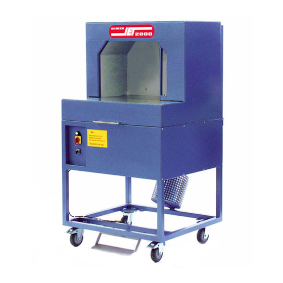
- Page 1 Translation of the original operating manual JET 2000 Strapping Machines Model range JET-OB SIEBECK GMBH D - 69412 EBERBACH Telephone 00496271-9208 0 Fax 00496271-9208 88 E-mail : info@siebeck.de Internet : www.siebeck.de...
-
Page 2: Table Of Contents
Contents Page Foreword Warranty Technical data Safety Set-up, start-up, maintenance Control elements Inserting the cord 9 - 10 Operating the machine Zero test / adjustment Stripper setting Faults and their causes Knot - story 15 – 16 Recommended stock of spare parts Spare parts –... -
Page 3: Foreword
If this machine is sold or set up elsewhere, then this instruction manual must be given to the new owner or the new user. Additional copies may be ordered from the address given below. SIEBECK GmbH PO Box 1145 D - 69401 Eberbach Telephone 00496271-92080 Fax 00496271-920888 E-mail : info@siebeck.de www.siebeck.de... -
Page 4: Warranty
WARRANTY All the machines that have been manufactured in our production facilities have a 12-month warranty from the start-up, or 18 months after the delivery. This warranty relates to material and manufacturing defects. The warranty covers all parts, with the exception of wear and tear parts and parts, which are replaced as a result of normal wear in the maintenance. -
Page 5: Technical Data
Technical data Machine dimensions: OB 50 1810 1220 660 OB 65 2040 1530 660 OB 100 2515 2220 660 110 1000 1000 all dimensions in mm – subject to change Machine capacity: 25 to 45 cycles per minute (depending on machine type) Machine weight: OB 50 –... -
Page 6: Safety
Safety! The European standard EN 60204-1 requires that power be supplied via an appropriate plug and socket device. Connecting the power supply cable directly, without a plug to a power distributor is therefore prohibited. The safety limit switches 4S1 and 4S2 prevent the machine from starting when the side door is open. - Page 7 Set-up and start-up Make sure the operating voltage is correct before starting up the machine. Operating voltage: Unless otherwise specified, the machine is set on delivery ex works at 400 Volt alternate current 50 Hz. Measure local mains voltage and compare with the specification on the rating plate.
-
Page 8: Control Elements
Control elements On the control panel cover on the front of the machine, you will find the following control elements: On- off switch Switch position ”0“ Machine ”off“ Switch position “1“ Machine ”on“ Indicator light signals the presence of voltage, and the correct direction of rotation Selector switch (1-4) - for single- to multiple strapping... -
Page 9: Inserting The Cord
Inserting the cord When the machine leaves our premises, it is fully threaded with a piece of cord. Carefully study the course of the cord and you will be able to understand the following description more easily. Proceed as follows based on the threading diagram opposite: Loosen the spring cap (A) on the reel case and fold lid back Remove fastening nut (B) for cord reel Insert cord reel and press against the foam rubber inlay (D). - Page 10 Inserting the cord 1 3 5 7 2 4 6...
-
Page 11: Operating The Machine
Operating the machine Procedure 1. Single strapping Set on- off switch to switch position “1“. Selector switch (1-4) to switch position ”1“. The product to be strapped is set on the machine table. The left side of the product must lie against the left tunnel wall. Push the product back across the strapping level until the desired strapping position is reached. -
Page 12: Zero Test / Adjustment
Zero test The correct zero setting of the knotting unit is achieved, if the track roller of the injector lever is 2-4mm before the curve drops. __________________________________________________________... - Page 13 Zero adjustment Loosen the hexagon screw marked in the drawing above, adjust the limit switch operating vane up or down, until the correct zero point is reached after the next rotation of the unit.
-
Page 14: Stripper Setting
Stripper setting The lateral setting of the stripper is done via the threaded pin No. 9 (Group M4). In the backwards movement of the knotter, the stripper should lie with pressure against the knotter. The height is adjusted via the joint head No. 2 (Group M4). The Figure below shows the correct height of the stripper slot to the knotter. -
Page 15: Faults And Their Causes
Faults and their causes Never re-work the surface of the clamp housing! This area has a precisely defined contour. The dent is intentional and is not caused by wear and tear. Only make any adjustments required by adjusting the thread brake and clamp – spring. 1. -
Page 16: Knot - Story
The knot story Faulty knots and causes Short loops Knotter opens too soon. Mount for track roller Move knotter opening backwards in the direction of the chain wheel. Stripper is not against the knotter. STRING too thin. Knot not tight enough Stripper slot too big. - Page 17 A normal long and a short loop Knotter not closing properly. Tension spring of the Knotter lock too weak. Stripper not lying against the knotter. Single loop The knot has only a single loop; the second loop is pulled through. Increase spring pressure on the clamp.
Need help?
Do you have a question about the JET Series and is the answer not in the manual?
Questions and answers