Advertisement

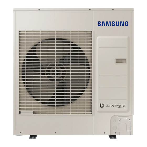
Air conditioner
Installation manual
AC***TXAP*G
• Thank you for purchasing this Samsung air conditioner.
• Before operating this unit, please read this manual carefully and retain it for future
reference.

Advertisement

Table of Contents
loading

Summary of Contents for Samsung AC TXAP G Series

  • Page 1 Air conditioner Installation manual AC***TXAP*G • Thank you for purchasing this Samsung air conditioner. • Before operating this unit, please read this manual carefully and retain it for future reference.
  • Page 2: Table Of Contents

    Contents Safety Information General information Installing the unit Power supply line, fuse or circuit breaker Installation Procedure Step 1 Choosing the installation location Step 2 Fixing the outdoor unit in place Step 3 Connecting the power cables, communication cable, and controllers Step 4 Optional: Extending the power cable Step 5 Connecting the refrigerant pipe Step 6 Optional: Cutting and flaring the pipes...
  • Page 3 Maintenance Procedures Performing the gas leak tests for repair Decommissioning Appendix Troubleshooting Correct Disposal of This Product (Waste Electrical & Electronic Equipment) (Applicable in countries with separate collection systems) This marking on the product, accessories or literature indicates that the product and its electronic accessories (e.g. charger, headset, USB cable) should not be disposed of with other household waste at the end of their working life.
  • Page 4: Safety Information

    • This manual explains how to install an indoor unit • Do not pierce or burn. with a split system with two SAMSUNG units. The use • Be aware that refrigerants may not contain an odour. of other types of units with different control systems may damage the units and invalidate the warranty.
  • Page 5: Installing The Unit

    • For use in Europe: This appliance can be used by • For this reason, when provisions of the installation children aged from 8 years and above and persons manual are not complied with, the cost required to with reduced physical, sensory or mental capabilities access and repair the units (in SAFETY CONDITIONS, or lack of experience and knowledge if they have as set out in prevailing regulations) with harnesses,...
  • Page 6: Power Supply Line, Fuse Or Circuit Breaker

    Safety Information • Make sure that the work area is safe from flammable • Never directly touch any accidental leaking substances. refrigerant. It could result in severe wounds caused by frostbite. • To purge air in the refrigerant, be sure to use a vacuum pump.
  • Page 7: Installation Procedure

    200 mm Minimum required room area – Air Guide Duct (This product is not provided by Samsung) • IMPORTANT: it’s mandatory to consider either the • Install the unit at a height where its base can be table 1 or taking into consideration the local law firmly fixed in place.
  • Page 8 Installation Procedure CAUTION CAUTION • You have just purchased a system air conditioner • Depending on the condition of power supply, unstable and it has been installed by your installation power or voltage may cause malfunction of the parts specialist. or control system.
  • Page 9 Minimum clearances for the outdoor unit When installing 1 outdoor unit (Unit: mm) or more or more or more or more 300 or more 300 or more 1000 150 or 150 or or more more more CAUTION or more • The outdoor unit must be installed according to the specified distances in order to permit accessibility from each side, to guarantee correct operation, maintenance, and repair of the unit.
  • Page 10: Step 2 Fixing The Outdoor Unit In Place

    Installation Procedure Moving the outdoor unit with wire rope CAUTION • Install a drain outlet at the lowest end around the 1 Before carrying the outdoor unit, fasten two wire base for outdoor unit drainage ropes of 8 m or longer, as shown in the figure. •...
  • Page 11: Step 3 Connecting The Power Cables, Communication Cable, And Controllers

    Step 3 Connecting the power cables, Air conditioning system examples communication cable, and controllers When using earth leakage circuit breaker (ELCB) for a single phase You must connect the following three electrical cables to the outdoor unit: Communication cable Main power •...
  • Page 12 Installation Procedure Connecting the main power cable When using ELB for 1 phase and 3 phase 1-phase Electrical component box Power supply 1(L) 2(N) MCCB Cable tie Outdoor-to- Main power Communication cable indoor power cable cable 3-phase 1(L) 2(N) L1(R) L2(S) L3(T) The appearance of the unit may be...
  • Page 13 Main power terminal block specifications • 1-phase terminal block specifications • 3-phase terminal block specifications (Unit: mm) (Unit: mm) AC090/100/120/140/160/TXAPKG AC100/120/140/160/TXAPNG 1(L) 2(N) 1(L) 2(N) L1(R) L2(S) L3(T) 10.1 10.1 16.3 11.4 14.2 11.4 Main power cable specifications The power cable is not supplied with air conditioner. •...
  • Page 14 Installation Procedure 3-phase Model Outdoor unit Input current (A) Power supply Voltage range (V) Outdoor unit Indoor unit Outdoor unit Indoor unit Total MCA (A) MFA (A) Rated Min. Max. Cooling Heating AC100TNHDKG AC100TXAPNG 18.8 18.8 18.8 AC120TNHDKG AC120TXAPNG 19.0 19.0 19.0 380 to 415...
  • Page 15 Silence mode controller wiring diagram 3-phase Outdoor unit Indoor Unit Outdoor Unit ASSY Control out 1(L) 2(N) L1(R) L2(S) L3(T) Cable tie Outdoor-to-indoor 3-phase 4-wire main Communication Non-voltage contact power cable (AC 380V) power cable cable Connecting the outdoor-to-indoor power cable NOTE and the communication cable •...
  • Page 16 Installation Procedure DRED wiring diagram Cable specification Model Power cable Interconnection cable Outdoor unit 4 Wires, 0.75mm² ASSY Control out AC***TXAPKG ±10% H07RN-F (60245 IEC66) (Only for reference) Outdoor-to-indoor power terminal specifications • Connect the cables to the terminal board using the compressed ring terminal.
  • Page 17: Step 4 Optional: Extending The Power Cable

    • Connect the rated cables only. Outdoor-to-indoor power and communication cables specifications • Connect using a driver which is able to apply the rated torque to the screws. • If the terminal is loose, fire may occur caused by arc. Indoor power supply If the terminal is connected too firmly, the terminal Power supply...
  • Page 18 Installation Procedure 2 As shown in the figure, peel off the shields from the 4 Using a crimping tool, compress the two points and rubber and wire of the power cable. flip it over and compress another two points in the same location.
  • Page 19: Step 5 Connecting The Refrigerant Pipe

    7 After tube contraction work is completed, wrap it with Step 5 Connecting the refrigerant pipe the insulation tape to finish. Three or more layers of insulation are required. Maximum allowable length Items Single Installation Method 1 Method 2 Insulation tape AC100TXAP*G IInsulation tape Applicable outdoor...
  • Page 20: Step 6 Optional: Cutting And Flaring The Pipes

    Installation Procedure Step 6 Optional: Cutting and flaring the CAUTION pipes • Be sure to use C1220T-1/2H (Semi-hard) pipe for more than Ø19.05 mm. If you use C1220T-O (Soft) 1 Make sure that you have the required tools available. pipe for Ø19.05 mm, the pipe may be broken, which (pipe cutter, reamer, flaring tool, and pipe holder) can result in an injury.
  • Page 21: Step 7 Installing Oil Traps

    5 Check that the flaring is correct, referring to the • Never install a dryer to this unit in order to guarantee illustrations below for examples of incorrect flaring. its lifetime. • If the pipes require brazing ensure that OFN(Oxygen Free Nitrogen) is flowing through the system.
  • Page 22: Step 8 Connecting Up And Removing Air In The Circuit

    Installation Procedure Step 8 Connecting up and removing air 3 Connect the charging hose of low pressure side of manifold gauge to the packed valve having a service in the circuit port as shown at the figure. CAUTION CAUTION • When installing, make sure there is no leakage. When •...
  • Page 23: Step 9 Adding Refrigerant (R-32)

    8 Check for gas leakage. 1 Check if the stop valve is closed completely. • At this time, especially check for gas leakage from 2 Charge the refrigerant through the service port of the the 3-way valve’s stem nuts(A port), and from the liquid stop valve.
  • Page 24 Installation Procedure Please fill in the following with indelible ink on the (Unit: g) refrigerant charge label supplied with this product and Model on this manual. AC090TXAPKG 3600 2700 • : The factory refrigerant charge of the product. AC100TXAP*G 5575 3100 2475 •...
  • Page 25: Step 10 Performing The Gas Leak Test

    Calculating the quantity of refrigerant to add The quantity of additional refrigerant is variable according to the installation situation. Thus, make sure the outdoor unit situation before adding refrigerant. This operation can only be performed by a qualified refrigeration specialist. A(Gas) Single installation outdoor unit B(liquid)
  • Page 26: Step 11 Connecting The Drain Hose To The Outdoor Unit

    Installation Procedure Step 11 Connecting the drain hose to Step 12 Insulating the refrigerant the outdoor unit pipes When using the air conditioner in the heating mode, ice Once you have checked that there are no leaks in the may accumulate . During de-icing (defrost operation), system, you can insulate the piping and hose.
  • Page 27: Step 13 Checking The Earthing

    Step 13 Checking the earthing Insulation Type (Heating/Cooling) If the power distribution circuit does not have a earthing High Standard Pipe size or the earthing does not comply with specifications, an humidity Pipe Remarks (mm) [Less than earthing electrode must be installed. The corresponding [over 30°C, 30°C, 85%] accessories are not supplied with the air conditioner.
  • Page 28: Step 14 Performing Final Check And Trial Operation

    Installation Procedure ※ Defrost test mode 5 Carefully check the installation by measuring the earthing resistance with a earth resistance tester. If Condition 1: The outdoor temperature is below 10°C. the resistance is above the required level, drive the Condition 2: All the temperature conditions should meet electrode deeper into the ground or increase the the defrost conditions.
  • Page 29 6 View mode: When the K4 switch is pressed, you can see information about our system state as below. short Display contents SEG1 SEG2 SEG3 SEG4 Unit push Order frequency Hundreds digit Tens digit Units digit Current frequency Hundreds digit Tens digit Units digit The number of preset...
  • Page 30 Installation Procedure 7 Setting outdoor unit option switch and address • After selecting the function for options, press and manually hold the K2 switch for 2 seconds. Edited value of the option will be saved when entire segments a Setting the option blinks and tracking mode begins.
  • Page 31: Extra Procedures

    Extra Procedures Pumping down refrigerant Relocating the indoor and outdoor units WARNING 1 Pump down refrigerant. See Pumping down • After installing the product, be sure to perform leak refrigerant on page 31. tests on the piping connections. After pumping down 2 Remove the power cord.
  • Page 32: Using The Stop Valve

    Extra Procedures Using the stop valve NOTE • Do not apply excessive force to the stop valve and always use special instruments. Otherwise, the Opening the stop valve stopping box can be damaged and the back sheet can leaks. 1 Open the cap and turn the stop valve anticlockwise •...
  • Page 33 Maintenance Procedures Performing the gas leak tests for repair Decommissioning In case of repair of the refrigerant circuit, the following The following requirements must be fulfilled before and procedure must be kept to consider flammability. while taking the decommissioning procedure: •...
  • Page 34 Appendix Appendix Troubleshooting The table below list the self-diagnostic routines. For some of error codes, you must contact an authorized service centre. If an error occurs during the operation, it is displayed on the outdoor unit PCB LED, both MAIN PCB and INVERTER PCB.
  • Page 35 No. Error Code Meaning Remarks E458 Fan speed error FAN1 ERROR E461 Error due to operation failure of inverter compressor E462 System stop due to full current control E463 Over current trip / PFC over current error Check OLP sensor 1.
  • Page 36 This appliance is filled with R-32. DB68-08522A-00...

Table of Contents