Challenge MEDALIST 820 Instructions And Parts Manual

Challenge MEDALIST 820 Instructions And Parts Manual

Air feed table model folder
Table of Contents

Advertisement

Quick Links

The Challenge Machinery Company provides owner's manuals on its
products solely as a courtesy to its customers. See the information below
before using this manual.
These manuals are for reference only. These manuals include products which are noncurrent,
unsupported or no longer produced by The Challenge Machinery Company, and are provided solely as
an accommodation to our customers. By providing these manuals, The Challenge Machinery Company
makes no representation or warranty as to the products, their current condition, or their suitability or fitness
for use in any particular application, which are the sole and independent responsibility of the product
owner and user.
Older products may not comply with current safety procedures, guidelines or regulations, and it
is the product owner's and user's responsibility to evaluate the suitability and fitness of the
products in their current use and application. The Challenge Machinery Company makes no
representation, warranty or recommendation regarding any modifications which may be required
on non-current or unsupported products. The Challenge Machinery Company assumes no liability
for any modification or alteration to any Challenge product, and any such modification or
alteration to any Challenge product is not authorized by The Challenge Machinery Company. The
availability of these manuals is solely for the purpose of providing reference information for the products.
This manual may not be complete in all aspects of product maintenance and repair. All products should
be used only by qualified and properly trained personnel, following proper safety procedures. All
products should be regularly inspected and maintained, and their condition, application and use should
be periodically evaluated by qualified personnel. Only qualified and properly trained technicians should
perform maintenance, repair and replacement procedures. Attempting these procedures without proper
training may cause machine damage or operator injury!
Products may be unsupported by The Challenge Machinery Company due to age or the unavailability of
parts from their original manufacturer. No parts or product support will be available to repair or maintain
unsupported products. Older products may not be UL listed (if the product does not have a UL label it is
not a listed product), and may not comply with applicable installation or other regulations or requirements
if relocated to a new facility. Many municipalities require a product to be UL listed before an electrician
will connect power to them. Often the cost of updating an older product to comply with current safety
regulations is greater than the value of the product.
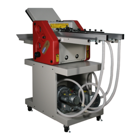
MEDALIST 820/870
Instruction and Parts Manual
Serial Numbers:
961533 through 159999,
870-A-150000 and up
Sold and Serviced by
The Challenge Machinery Company
6125 Norton Center Drive
Norton Shores, MI 49441-6081 USA
F.669-D
ChallengeMachinery.com
August 2015

Advertisement

Table of Contents
loading

Summary of Contents for Challenge MEDALIST 820

  • Page 1 Products may be unsupported by The Challenge Machinery Company due to age or the unavailability of parts from their original manufacturer. No parts or product support will be available to repair or maintain unsupported products.
  • Page 2: Introduction

    DIRECT TO CHALLENGE. If you bought a used machine, it is important to have the following information on record at Challenge. Copy this page, fill in the information and send it care of: The Challenge Service Department, 6125 Norton Center Drive, Norton Shores, MI 49441-6081.
  • Page 3: Packing List

    (fig. 1) Medalist Air Feed Table Model Folder (870 shown with stand) PACKING LIST Your folder has been carefully packaged to prevent damage in shipment. Inspect all shipments as soon as they are received. Note any signs of damage on the freight bill and notify the claims department of the carrier within 15 days.
  • Page 4: Table Of Contents

    TABLE OF CONTENTS INTRODUCTION................... 2 PACKING LIST .................... 3 SPECIFICATIONS ..................5 SAFETY PRECAUTIONS ................6 CAUTION: POWER LOCKOUT PROCEDURE ..........6 WARNING LABEL DEFINITIONS ..............7 INSTALLATION .................... 8 Cleaning ....................10 Power Hookup ..................11 Power Controls ..................11 Control Panel..................
  • Page 5: Specifications

    A - Weighted sound power level at operator level 6 ft. (1.83m); folding 20lb (75g/m ), 8-1/2” x 11” (216X279mm) Machine Folding: 101 dB Challenge reserves the right to make changes to any product or specification without notice and without incurring responsibility to existing units. F.669-D/820-870/Jan 98...
  • Page 6: Safety Precautions

    • READ and understand all instructions thoroughly before using the machine. If questions still remain, call your Authorized Challenge Dealer - Failure to understand operating instructions may result in personal injury. •...
  • Page 7: Warning Label Definitions

    WARNING LABEL DEFINITIONS SINGLE OPERATOR Do not operate with more than one person. SHOCK HAZARD Disconnect power before removing cover. Replace cover before operation. SHOCK HAZARD Disconnect power before removing cover. Replace cover before operation. HAZARDOUS AREA Disconnect power before cleaning, servicing, or mak- ing adjustments not requiring power.
  • Page 8: Installation

    INSTALLATION the rail guides, (fig. 4), and tighten the eccentric plate Note: For Right Angle & Crosscarrier assembly see locks, (fig. 6). Note both plates have two sets of locat- page 20. Open the stand carton first and assemble ac- ing holes in the plate rails.
  • Page 9 Locating Pins/ Feeder Notch (fig. 7) (fig. 10) side frames. Install the feed table so the notches in the 7. Attach the stacker wheel assembly to the tie bar side brackets, (fig. 7), mate with the mounting pins in- next to the jam detector, as shown, fig. 10. side the folder side frames.
  • Page 10: Cleaning

    Cleaning A clean machine will reflect in the quality of the work it produces. As you unpack your folder, wipe off any excess protective oil, dirt, or dust which may have ac- cumulated during shipping. Keep your machine clean, and wipe off any accumulations of paper dust at the end of each day.
  • Page 11: Power Hookup

    Power Hookup Control Panel The standard Medalist Folder requires a 120 volt, 20 amp circuit with a three-prong, grounded receptacle. Speed Sheet Control Roller It is the customer's responsibility to provide a power Counter Motor Compressor Counter line that meets all local electrical codes. Reset Motor Optional 50 Hz, 240 volt machine draws 10 amps.
  • Page 12: Squaring

    OPERATION Squaring In order for your machine to fold stock squarely, it must 3. Raise the sheet separator (ccw) so it is away from be fed into the rollers square. Your Medalist has been the sucker wheel (fig. 19). Place a sheet of the paper adjusted at the factory and should only require peri- to be folded on the feed table.
  • Page 13: Feeding Paper

    3. Place a one inch wide (25mm), double thickness piece of stock to be folded under the tip of the separa- tor plate, (fig. 19). Lower the separator (cw) until there (2a) Knob is a slight drag on the paper as it is pulled from under the separator.
  • Page 14: Bleeder Valve (Vacuum Adjustment)

    There is a bleeder valve on the vacuum pump, (fig. 23), which allows for vacuum adjustment from com- pletely off to completely on. General settings for the Separator bleeder valve are half open for 20# stock, and closed Guide Lock for 80# and heavier stock.
  • Page 15: Roller Caliper Set Up (870 Only)

    Roller Calipers Micro-adjust Knobs (fig. 25) (fig. 27) To provide the proper clearance between rollers, 3/4" wide paper strips are inserted into the calipers, (fig. 27). Simply press the caliper lever and insert the cor- rect number of strips into the open gap. Put the same number of strips into both sides of the folder.
  • Page 16: Stacker

    Roller Caliper Quick Set Up Guide Roller calipers on the Medallist 870 feature quick set the sheet which will be the minimum thickness of the up calipers. Calipers adjust the space or tension be- stock passing between the rollers. Use 3/4" wide, cut tween rollers to provide the proper grip on the paper strips of the same material being folded.
  • Page 17 NOTES NOTES F.669-D/820-870/Jan 98...
  • Page 18: Special Applications

    SPECIAL APPLICATIONS CAUTION: Use extreme care when handling and changing the scoring or perforating blades. Severe lacerations could result from careless handling procedures. SLITTER ACCESSORIES Stacker Perf Springs Stripper Perf Slitter Slitter Wrenches Screws Collar Shaft Shaft Rubber Score Wheel Blade Perf Score...
  • Page 19: Perforating

    Perforating Perforating may be used to deliver a perforated sheet flat or as a guide for additional right angle folds. *NOTE: A stripper is required for each perforator blade. Stripper* Adjusting Screw Perforator Blade Perforator Collar (ill. 6a) Perforating The perforating blade (and any additional blades purchased in addition to the one supplied) is mounted on the upper shaft of the slitter assembly.
  • Page 20: Right Angle Crossfold System

    RIGHT ANGLE CROSSFOLD SYSTEM (fig. 32) Challenge offers a Right Angle Crossfold System which is used in conjunction with the Medalist The System consists of a second parallel unit, a cross- Button Head Button Head fold carrier table, shorter stand and a transfer assem-...
  • Page 21 NOTE: If you have purchased a crosscarrier kit as an after market addition to convert a second C. Install the electronic pigtail assembly so the ma- folder to a right angle, you will need to perform chines can electronically communicate with each other. three additional procedures (A –...
  • Page 22: Conveyor Set Up

    90° to the right, a simple kit is available from the factory to switch the direction of the crosscarrier. Contact your authorized Challenge Dealer for details. Instructions and parts included in the kit are as noted on the following pages.
  • Page 23: Optional Crossfold Conversion Kit 35537

    OPTIONAL CROSSFOLD CONVERSION KIT 35537 Marble CAUTION: Turn off the power to all units Holder and disconnect the power cords before disassembling or making any electronic con- nections. Marble Holder Shaft Shaft Shaft Mounting Mounting Block Block Standard Screws Delivery Shaft Shaft Drive Belt...
  • Page 24 9. Remove the four (4) screws, (fig. 41, pg 23), mount- 13. Remove the marble holder mounting shaft. ing the roller drive blocks and reposition from the “A” mounting holes to the “B” holes (ill. 8, INSET A). 14. Remove the squaring assembly hardware: squar- ing knob, wing nut, and spring, (fig.
  • Page 25: Maintenance

    (fig. 43) Pump Lubrication – Your Challenge folder uses an oil-less pump and motor. Do Not Attempt to lubricate the pump or motor. F.669-D/820-870/Jan 98...
  • Page 27: Notice

    Challenge. The Challenge Machinery Company assumes no liability for any modification or alteration to any Challenge products, and any such modification or alteration to any Challenge products is not authorized by The Challenge Machinery Company. Any modification or alteration of any Challenge product will void any remaining warranty.
  • Page 28: Model 820 Main Assembly - Left Hand Side

    F.669-D/820-870/Jan 98...
  • Page 29 F.669-D/820-870/Jan 98...
  • Page 30: Model 820 Main Assembly - Right Hand Side

    F.669-D/820-870/Jan 98...
  • Page 31 F.669-D/820-870/Jan 98...
  • Page 32: Model 820 Main Assembly - Front View

    F.669-D/820-870/Jan 98...
  • Page 33 F.669-D/820-870/Jan 98...
  • Page 34: Model 870 Main Assembly - Left Hand Side

    F.669-D/820-870/Jan 98...
  • Page 35 F.669-D/820-870/Jan 98...
  • Page 36: Model 870 Main Assembly - Right Hand Side

    F.669-D/820-870/Jan 98...
  • Page 37 F.669-D/820-870/Jan 98...
  • Page 38: Model 870 Main Assembly - Front View

    F.669-D/820-870/Jan 98...
  • Page 39 F.669-D/820-870/Jan 98...
  • Page 40: Foldplate Assembly #1

    FOLDPLATE ASSEMBLY #1 35061 REV. ‘C’ F.669-D/820-870/Jan 98...
  • Page 41 FOLDPLATE ASSEMBLY #1 35061 REV. ‘C’ F.669-D/820-870/Jan 98...
  • Page 42: Foldplate Assembly #2

    FOLDPLATE ASSEMBLY #2 35080 REV. ‘D’ F.669-D/820-870/Jan 98...
  • Page 43 FOLDPLATE ASSEMBLY #2 35080 REV. ‘D’ F.669-D/820-870/Jan 98...
  • Page 44: Feeder Assembly

    FEEDER ASSEMBLY 35100-2 REV. ‘F’ F.669-D/820-870/Jan 98...
  • Page 45 FEEDER ASSEMBLY 35100-2 REV. ‘F’ F.669-D/820-870/Jan 98...
  • Page 46: Stacker Assembly

    STACKER ASSEMBLY 35128-1 F.669-D/820-870/Jan 98...
  • Page 47: Long Stacker Assembly

    LONG STACKER ASSEMBLY (OPTIONAL) 35290-1 F.669-D/820-870/Jan 98...
  • Page 48: Stacker Wheel Assembly

    STACKER WHEEL ASSEMBLY 35198 REV. ‘E’ F.669-D/820-870/Jan 98...
  • Page 49: Caliper Assembly

    CALIPER ASSEMBLY 35041 F.669-D/820-870/Jan 98...
  • Page 50: Medalist Stand Assembly

    MEDALIST STAND ASSEMBLY 35470 REV. ‘C’ F.669-D/820-870/Jan 98...
  • Page 51: Right Angle Stand Assembly

    RIGHT ANGLE STAND ASSEMBLY 35473 REV. ‘C’ F.669-D/820-870/Jan 98...
  • Page 52: Jam Detector Assembly

    JAM DETECTOR ASSEMBLY EE-2607 REV. ‘C’ F.669-D/820-870/Jan 98...
  • Page 53: Electrical Sequence Of Operation

    ELECTRICAL SEQUENCE OF OPERATION ELECTRICAL SEQUENCE OF OPERATION A. Close the POWER switch. B. Press the compressor ON switch. C. Press the START button. D. Adjust the SPEED CONTROL. ELECTRICAL SCHEMATIC REFERENCES (Drawings E-2657 & E-2658) While the POWER switch is closed, power is brought to the transformer, provided the 8A fuse is conductive. The transformer provides power to the start/stop circuit, and to the sheet counter.
  • Page 54: 820 Basic Machine Schematic - (120 Volt)

    F.669-D/820-870/Jan 98...
  • Page 55: 820 Basic Machine Schematic - (230 Volt)

    F.669-D/820-870/Jan 98...
  • Page 56: 870 Basic Machine Schematic - (120 Volt)

    F.669-D/820-870/Jan 98...
  • Page 57: 870 Basic Machine Schematic - (230 Volt)

    F.669-D/820-870/Jan 98...
  • Page 58: 820/870 Back Cover Plate Assembly - (120 Volt)

    F.669-D/820-870/Jan 98...
  • Page 59 F.669-D/820-870/Jan 98...
  • Page 60: 820/870 Back Cover Plate Assembly - (230 Volt)

    F.669-D/820-870/Jan 98...
  • Page 61 F.669-D/820-870/Jan 98...
  • Page 62: 820 Control Panel Assembly

    F.669-D/820-870/Jan 98...
  • Page 63: 870 Control Panel Assembly

    F.669-D/820-870/Jan 98...
  • Page 64: 120/220 Volt Pump Assembly

    120/220 VOLT PUMP ASSEMBLY PP-270/PP-274 F.669-D/820-870/Jan 98...
  • Page 65 120 VOLT 60 HERTZ PUMP ASSEMBLY PP-270 220 VOLT 50 HERTZ PUMP ASSEMBLY PP-274 F.669-D/820-870/Jan 98...
  • Page 66: Standard Accessories

    STANDARD ACCESSORIES AA-11214 F.669-D/820-870/Jan 98...
  • Page 67 STANDARD ACCESSORIES AA-11214 NOTE: If desired item #14 replaces knob (item #20, pg 44). F.669-D/820-870/Jan 98...
  • Page 68: Cross Carriage Assembly

    F.669-D/820-870/Jan 98...
  • Page 69 F.669-D/820-870/Jan 98...
  • Page 70: Transfer Assembly

    F.669-D/820-870/Jan 98...
  • Page 71 F.669-D/820-870/Jan 98...
  • Page 72: Crossfold Electrical Hook-Up

    CROSSFOLD ELECTRICAL HOOK-UP K-2670-i F.669-D/820-870/Jan 98...
  • Page 73: Crossfold Electrical Hook-Up Instructions

    CROSSFOLD ELECTRICAL HOOK-UP INSTRUCTIONS WARNING: Shock Hazard! Disconnect and lockout the power to both machines before proceeding with the following instructions. Crossfold Folder Power Panel Connections Operation - Crossfold System (Steps 1-4) To run the two machines together as a Right Angle 1.
  • Page 74: Imposition Manual

    IMPOSITION MANUAL When planning a form, check your folded “Dummy” Some of the most common impositions are illustrated for proper page numbers and correct guide edges. in the next pages. These appear for reference only and do not imply suitability or practicality. As illustrated, the sheets are visualized lying on the feed table.
  • Page 75 THE FOLLOWING LAYOUTS REQUIRE THE USE OF THE CROSSFOLD SYSTEM (DESIGNATED BY ‘Right Angle’ IN THE ILLUSTRATIONS BELOW). EIGHT PAGE 2 R A OBLONG EIGHT PAGE RIGHT ANGLE Use Plates: Parallel - #1 Use Plates: Parallel - #1 Right Angle - #1 Right Angle - #1 TWELVE PAGE,LETTER FOLD ACCORDIAN TWELVE PAGE BOOK, SADDLE STITCH...
  • Page 76: Slitter Shaft Assembly Components

    F.669-D/820-870/Jan 98...
  • Page 77: Slitter Shaft Assembly Components

    F.669-D/820-870/Jan 98...
  • Page 78: Roller Replacement Repair Kits

    MFG-016 “O” Ring drive belt 35179-1 Out feed tires A-10249 Tech notes MFG-016 “CHALLENGE WILL NOT ACCEPT RETURN OF SUGGESTED PARTS NOT USED IN A REBUILD” 870 RUBBER ROLLER REBUILD KIT: K-35293 Rubber rollers 35051 Roller gears 35052 Gear keys...
  • Page 79 NOTES F.669-D/820-870/Jan 98...
  • Page 80 © 1996 by The Challenge Machinery Company. All rights reserved. Printed in the U.S.A. F.669-D/820-870/Jan 98...

This manual is also suitable for:

Medalist 870

Table of Contents