Table of Contents
Advertisement
Advertisement
Table of Contents

Related Manuals for Righton Retinomax Screeen

Summary of Contents for Righton Retinomax Screeen
- Page 1 Hand Held Auto Refractometer Instructions November 2018 D054-E...
- Page 2 CAUTION: Please read this instruction manual before using the instrument. This instruction manual is intended for users of the Retinomax Screeen. It includes instructions on how to use the instrument, safety handling precautions, and specifications. These instruments conform to the Japanese Industrial Standards (JIS) as well as the standards of the International Electrotechnical Commission (IEC).
-
Page 3: Table Of Contents
CONTENTS Handling Precautions - Please first read for safety purposes ..........5 ■ EMC (Electromagnetic Compatibility) ................11 ■ Overview ........................16 Instrument Overview, Components and Options ..........16 Instrument Classification ..................17 Symbols on the Instrument ................... 18 Labels and Marks ....................20 Name of Parts ...................... - Page 4 Various Functions ....................54 4-4-1 Pupil Diameter Measurement Function ............54 4-4-2 Alignment Direction Indication Function ............56 4-4-3 Focus Assist Function ..................57 4-4-4 Astigmatic Axis Correction Function .............. 59 4-4-5 AUTO QUICK Mode ..................63 4-4-6 Retroillumination Mode .................. 65 4-4-7 Storing Data ....................
- Page 5 5-11 VERSION Confirmation [VERSION] ..............97 Connecting to External Instruments ................98 Wireless Transmission to the Remote Vision RV-II ..........98 Connecting to Computer via USB ................. 98 Maintenance ......................... 99 Checking the Measurement Accuracy ..............99 Replacing the Print Roll ..................99 Replacing the Fuses ...................
-
Page 6: Handling Precautions - Please First Read For Safety Purposes
■Handling Precautions - Please first read for safety purposes <Caution Symbols Used in This Manual> Righton products are manufactured with full attention to safety. However, these instruments can cause personal injury or equipment damage if used improperly or if the instructions are ignored. - Page 7 CAUTION 4. Installation and transport • Do not place the instrument and the peripheral equipment (PC, monitor) on an unstable location, such as a shaky table or inclined surface. It could be dropped or fall and cause injury. • Hold the main unit using the grip. Do not hold it with the LCD or forehead rest. •...
- Page 8 • This instrument is not waterproof. It should not be used or placed in a place where it can be exposed to liquid such as rainwater, beverages or chemicals. • If dew condensation occurs, allow the dew to disappear before using the instrument.
- Page 9 • Do not put any objects around power switch of the station or the printer to not disturbing emergency operation. • Do not lean on the units. • Please clean according to the specified method on the manual. If not follow, it may cause deterioration or damage to the unit.
- Page 10 • After use, turn off the power switch of the station and put on the dust cover. • If you plan to put the instrument out of service for a long time, pull the power cord out from the receptacle outlet. Also, remove the batteries from the main unit and keep them for later use.
- Page 11 • When charging the battery pack, do not place any cover over the main unit, the station, or the printer. If a cover is used, the heat generated in the main unit, the station, or the printer during charging may cause fire. In addition, the service life of the battery pack will be reduced by the additional load due to such a cover.
-
Page 12: Emc (Electromagnetic Compatibility)
The Electromagnetic Compatibility Directive sets the essential requirements for electrical and electronic equipment that may disturb or even be disturbed by other equipment. The Retinomax Screeen complies with these requirements as tabled below. Follow the guidance on the tables for use of the device in the electromagnetic environment. - Page 13 3.0m (C)EMC (IEC60601-1-2:2014) Emission guidance Retinomax Screeen is intended for use in the electromagnetic environment specified below. The customer or the user of the Retinomax Screeen should assure that they are used in such an environment. Emissions test Basic EMC standard or test method...
- Page 14 *6: Before modulation is applied. *7: This test level assumes a minimum distance between the ME EQUIPMENT or ME SYSTEM and sources of power frequency magnetic field of at least 15 cm. if the RISK ANALYSIS shows that the ME EQUIPMENT or ME SYSTEM will be used closer than 15 cm to sources of power frequency magnetic field, the IMMUNITY TEST LEVEL shall be adjusted as appropriate for the minimum expected distance.
- Page 15 *15: Applicable to ME EQUIPMENT and ME SYSTEMS with RATED input current less than or equal to 16 A / phase and ME EQUIPMENT and ME SYSTEMS with RATED input current greater than 16 A / phase. *16: Applicable to ME EQUIPMENT and ME SYSTEMS with RATED input current less than or equal to 16 A / phase.
- Page 16 Test Specifications for ENCLOSURE PORT IMMUNITY to RF wireless communications equipment Test Maximum Distance IMMUNITY Band Service Modulation Frequency power TEST LEVEL (MHz) (V/m) (MHz) Pulse 380-390 TETRA400 Modulation 18Hz GMRS460 430-470 ±5kHz deviation FRS460 1kHz sine Pulse LTE Band 13, 704-787 modulation 217Hz...
-
Page 17: Overview
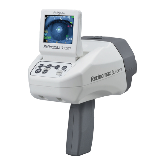
The pupil diameter measurement measures the pupil size in the horizontal and vertical directions. This instrument consists of a main unit (Retinomax Screeen), Station (Retinomax Station 5), and Printer (Retinomax Printer 5). Device and printer could be carried with ease, and contains battery, make it easier to measure and print out in small spaces. -
Page 18: Instrument Classification
● Fuses (2) (φ5 x 20 mm250 V, T1.6 AH (021501.6XP)) ● Power cord (1) ● Instruction manual (1) ● Dust cover (1) ■ Options ● Carrying case ● Battery pack Instrument Classification <Classification as per 93/42/EEC (MDD)> Class IIa <Protection type against electric shock>... -
Page 19: Symbols On The Instrument
<Degree of safety for use in a flammable environment> Retinomax Screeen is not designed to be used in a flammable environment. Do not use it in a flammable environment. <Disinfection method approved by the manufacture> If necessary, clean the forehead rest with soft cloth soaked with rubbing alcohol. - Page 20 : The lamp indicated by this symbol on the station illuminates while the battery is charged. : This symbol means that this equipment has been certified as NRTL (National Recognized Testing Laboratories) by UL (Underwriters Laboratories). : This symbol means this equipment conforms to Medical Device Directive (93/42/EEC) in EU.
-
Page 21: Labels And Marks
Labels and Marks The product includes labels and marks to draw user's attention to important information and precautions. If you found some scratch or rack of words, please contact to dealer whom you purchased from. Main unit ● Bottom ● Manufacture date Type B applied part ●Battery part... - Page 22 Station ● ●Rear of the station Manufacture date...
- Page 23 Printer ● Bottom ● Manufacture date Battery part ●...
- Page 24 Battery pack ●...
-
Page 25: Name Of Parts
Name of Parts ■ System configuration Main unit Printer Station Main Unit Patient side ● Target line for measuring window lateral position Forehead rest Measuring part Center of measuring window Target line for measuring window height position Right/Left eye sensor Lighting part in CHILD mode Data transmission window... -
Page 26: Operation Panel
Operator side ● LCD Screen With tilt function 20° to 120° Operation panel Eyelet for neck strap Grip cover Grip Operation Panel Image of the operation panel ● Explanation and operation for main symbols ● Symbol Operation Explanation Turn the power on / off. Symbol will change depends on the battery pack’s capacity. - Page 27 Symbol Operation Explanation Symbol turns on and eyes(right/left) are discriminated automatically. AUTO When push again or push , switch to Push manual setting of right/left eyes discrimination and symbol turns off. Please select the right/left eye to observe with Switch to right eye measurement and symbol turns Push When push during lighting, switch to manual...
-
Page 28: Station
Station Front ● Contacts for charging the main unit (4) Contacts for connection to Accessories printer (5) mount Power indicator lamp Charge lamp for main unit Charge lamp for printer ●Accessories mount Place the model eye mounted Fuse Model eye... -
Page 29: Printer
Rear ● Power switch Power cord socket Power lamp lighting patterns Completed Charging charging Power indicator lamp Blue Blue Charge lamp for the main unit Orange Charge lamp for the printer Orange Printer Indication lamp Paper cover Power switch Lever opening/closing of paper cover Data receiving... - Page 30 Printing part USB port Indicator lamp lighting patterns Situation Indicator lamp Power off At battery driving: battery capacity more than 50% Green At battery driving: battery capacity approx. 10 to 50% Orange At battery driving: battery capacity less than approx. 10% Orange (blinking) Station suppling power Blue...
-
Page 31: Setup
Setup Attaching/Detaching the Strap Attach the strap to the eyelets of the main unit. Step 1 Step 2 Step 3 Step 4 CAUTION ・When moving the instrument while it is in operation, hang it from your neck using t h e strap and hold the grip. Dropping the instrument may lead to injury or damage. -
Page 32: Printer
3-2-2 Printer Turn the printer over. Open the battery cover by pressing ① with your fingers and sliding in direction ②. To make the indication ▽of the battery pack to the direction of ③, fit in the battery pack with the clicks, slide the battery pack to ④ to install. To remove the battery pack, slide it to reverse direction of ④. -
Page 33: Charging The Battery Pack
Charging the Battery Pack Be sure to read the following precautions before starting charging. ■Handling Precautions - Please first read for safety purposes Caution 7 • 3-4 Charging the Battery Pack ■Charging precautions • User Manual enclosed with the battery pack •... -
Page 34: Automatic Charging Of The Main Unit
CAUTION ・Only use the RT-01XR battery pack, which is our designated lithium ion battery. Useo f any other battery voids the operation warranty. ・The battery provided with Retinomax, Retinomax 2, Retinomax 3 cannot be use. ・Never disassemble or modify the battery pack. ・Never short-circuit the terminal of the battery pack. -
Page 35: Automatic Charging Of The Printer
CAUTION ・When connecting the printer to the station, make sure to use the one provided w i t h Retinomax Screeen or Retinomax K+Screeen. ・Do not use the printer provided with Retinomax, Retinomax 2, Retinomax 3. 3-4-3 Charging a Spare Battery Pack Insert the battery pack you want to charge into the printer and charge it. -
Page 36: Measurement
Measurement Measurement Procedure ● Power on Display of the opening screen Display of the measurement screen Confirmation of the setting Calibration with model eyes Explanation for patients Prepare the forehead rest Positioning the measurement eye Before the measurement Select the measurement subject and start measuring Auto measurement mode (AUTO, AUTO2) CONT measurement mode CHILD/QUICK measurement mode... -
Page 37: Power On
Power on Press on the operation panel. The symbol turns on green and the opening screen appears. 4-1-1 Opening Screen After displayed opening screen, measurement standby screen is displayed. Measurement standby screen Opening screen 4-1-2 Measurement Screen Measurement target Ref measurement number of times Stored data sets/ Storable data sets Right eye/Left eye Battery capacity... - Page 38 Battery capacity More than 50% Less than 50% Less than 10% Right / Left eye indicator during measurement Right eye measurement by R/L eyes automatic discrimination Left eye measurement by R/L eyes automatic discrimination Right eye measurement by R/L eyes manual setting Left eye measurement by R/L eyes manual setting Measurement mode AUTO mode...
-
Page 39: Setting Confirmation
4-1-3 Setting Confirmation Confirm the setting with [SETUP] Subjects Setting contents EXIT Finish the [SETUP] MEASURE Change measurement setting OUTPUT Change output setting MEMORY Output and delete stored data CHILD Change CHILD mode setting OTHER Change other setting CLOCK Change time setting POWER OPTION Change power supply setting PATIENT No... - Page 40 Initialization settings are as follow. See “5. Setting Up the Instrument”. ■MEASURE TYPE AUTO - 12.0 AUTO STEP ■OUTPUT ■OUTPUT SETTING OUTPUT PRINT & USB PRINT ID USB FORMAT ■OUTPUT FORMAT MESSAGE ■CONT FORMAT OUTPUT DATA LAST5 MESSAGE ■ MEMORY OUTPUT NUMBER LAST30 PRINT...
- Page 41 ■OTHER BUZZER ALIGN CHART BRIGHTNESS AUTO PARALLEL FOCUS ASSIST AUTO QUICK ■ CLOCK 120V area MDY DATE-FORM 230V area DMY 120V area AM/PM TIME-FORM 230V area 24H ■ POWER OPTION STAND-BY 3MIN SHUT-DOWN 3MIN ■ PATIENT No. 0001...
-
Page 42: Measuring The Model Eye
4-1-4 Measuring the Model Eye Open the accessory case, and, place model eye. Make sure setting with AUTO mode and VD12.0mm. Focus on model eye and start measurement. *See “4-3-1 Automatic Measurement Mode (AUTO, AUTO2)” to be acknowledged how to measure. Exposure to light may lead to loss of measurement accuracy or failure of the measurement. - Page 43 Make sure that the model eye and measurement window are not dirty. If the surface of the measurement window becomes dirty with patients’ nose grease or fingerprints or dust, the measurement results may be affected. If the measured values are out of the above ranges, see “4-3-1 Automatic Measurement Mode (AUTO, AUTO2)”...
-
Page 44: Preparation For Patient
Preparation for Patient 4-2-1 Prepare the Forehead Rest When pushing the place at the following figure until it makes a sound, the forehead rest automatically comes out. When closing it, push there until it makes a sound. CAUTION ・If the patient moves frequently, especially a child, the case that injure their face, do n o t use forehead rest. -
Page 45: Before The Measurement
4-2-3 Before the Measurement Clean the forehead rest each patient with soft cloth soaked with rubbing alcohol. Patients tend to be a little nervous, because they do not know what will happen to them, so it is best to try to relax and give them enough explanation. Briefly explain the following: •... -
Page 46: Measurement Modes And Start Measuring
Measurement Modes and Start Measuring This instrument offers three measurement modes. Measurement mode is selected form SETUP menu. See “5-1 Measurement Setup [MEASURE]”. The operation of each measurement mode is shown on the following table. Measurement subject Measurement mode A:Auto measurement mode Start ↓... -
Page 47: Automatic Measurement Mode (Auto, Auto2)
4-3-1 Automatic Measurement Mode (AUTO, AUTO2) This enable you to REF measurement. The operation method of AUTO mode and AUTO2 mode is the same. Enter to [SETUP] with , select measurement mode “AUTO” or “AUTO2” with <TYPE> in [MEASURE]. See “5-1 Measurement Setup [MEASURE]”. Make patient relaxed by talking to them, and, position the patients’... - Page 48 CAUTION ・When measurement, the case you make movement with the device right and l e f t , not to hit forehead rest to patient’s nose. ・It is safe that move it after separated from patient. With the patient's eye positioned approximately, look into the screen during the measurement.
- Page 49 Alignment direction indicator Horizontal indicator REF measurement screen The device judges the variation of the measurement data and it will automatically end when the measurement value becomes stable. If you want to finish the measurement in the middle of the measurement, press the measurement switch or switch the right/left eyes during measurement.
- Page 50 Completed both eyes measurement To print out the measurement results, aim the front side of the main unit toward the printer’s data receiving window, push button. When the memory function is on, the data is automatically memorized when the data is transferred. When the memory function is off, hold down for 2 seconds to save the data.
-
Page 51: Continuous Measurement Mode (Cont)
4-3-2 Continuous Measurement Mode (CONT) In this mode, measurement is performed continuously without finishing automatically. Enter [SETUP] with and set the measurement mode to “CONT” with <TYPE> in [MEASURE]. Take a measurement using the same procedure of 3 to 9 as in the “4-3-1 Automatic Measurement Mode (AUTO, AUTO2)”. -
Page 52: Child/Quick Mode
4-3-3 CHILD/QUICK Mode Press , the symbol will be blinking and goes on to CHILD mode. In CHILD mode, apply QUICK mode automatically in order to shorten the measurement time. Press again to goes on to QUICK mode, the symbol will be lighting and CHILD mode will be off. <CHILD mode>... - Page 53 LED blinking, lighting the fixation chart and melody ON/OFF in CHILD mode can be set with CHILD mode setting screen [CHILD] in [SETUP]. See “5-4 CHILD Mode Screen [CHILD]”. Perform the measurement in the same process as “4-3-1 Automatic Measurement Mode (AUTO, AUTO2)”...
- Page 54 <QUICK mode> The “Quick Measurement Mode” allows a shortening of the time from the start of measurement to display the measurement value. QUICK mode with short REF measurement time is useful in cases when measurement is difficult because of rapid eye movements due to nystagmus or if the patient is a child, or other reason.
-
Page 55: Various Functions
Various Functions 4-4-1 Pupil Diameter Measurement Function This instrument is equipped with a pupil diameter measurement with REF measurement. Enter to [SETUP] with , set <P-S> in [MEASURE] to “ONE” or “ALL”. ・When the <P-S> is “ONE”, pupil diameter is measured only once (first time) for each eye. - Page 56 If the pupil diameter less than 2.3mm, REF measurement value is displayed as “--”. When < P-S > is set to “ONE”, if the pupil size measurement value is less than 2.3 mm, pupil size measurement is performed again, and if it is 2.3 mm or more, normal measurement is performed.
-
Page 57: Alignment Direction Indication Function
Measurement completed screen when data cannot be obtained because the pupil size is less than 2.3 mm 4-4-2 Alignment Direction Indication Function The alignment direction indication function is used to indicate the direction for placing the refracted light from cornea within the alignment mark during the measurement. Move the main unit in the indicated directions, and measurements will be obtained more easily. -
Page 58: Focus Assist Function
4-4-3 Focus Assist Function This function notices that the range between instrument and eye is too close or too distant from the focus position. It is convenience function if it is not used to focus on the mire ring or want to measure at the exact position. - Page 59 The display is made according to the distance between the device and the eye to be examined as follows. Distance between the device and the eye setting close up and up and up and down: up and down: white up and down: white down: white down: white green...
-
Page 60: Astigmatic Axis Correction Function
4-4-4 Astigmatic Axis Correction Function (1) Horizontal Correction Function This is a function when the normal measurement, correct the astigmatic axis (AX) corresponding to the instrument inclination. At the measurement standby screen, hold down for 2 seconds. “AX-C” is displayed next to horizontal indicator, and the measured value is corrected in 1°... - Page 61 Measurement completed when horizontal correction is “ON” Printing example (2) Rotation Correction Function of Instrument If you need to perform measurement from 45°, 90°, or 135° rotated position, as for bedside measurement, astigmatic axis (AX) must be set appropriately. The rotation correction function corrects the astigmatic axis automatically from the rotated position.
- Page 62 Hold down on the operation panel for 2 seconds. The blinking arrow is displayed on the measurement screen and shift to the rotation corrected angle select screen. Corrected angle is displayed with “AX ” on right side of the screen. Press the measurement switch to change the rotation corrected angle.
- Page 63 Each corrected angle for right/left eye measurement is displayed on measurement completed screen. Rotation corrected angle Measurement completed screen with rotation correction function Printing example...
-
Page 64: Auto Quick Mode
4-4-5 AUTO QUICK Mode Refractive measurements may be difficult to obtain due to rapid eye movements in patients with nystagmus or children, or for other reasons. In such a situation, the AUTO QUICK mode function automatically activates the quick measurement mode which requires less time for measurement. - Page 65 When shifting to QUICK mode by AUTO QUICK mode, “AQ” is printed on the measured data. Printing example...
-
Page 66: Retroillumination Mode
4-4-6 Retroillumination Mode In the case of “the measured value varies”, “the confidence value is low”, etc., there may be foreign substances that obstruct measurement light such as opacity of the lens. For such patients, you can observe the optic media by using “Retroillumination mode”. Push to shift to retroillumination mode. -
Page 67: Storing Data
4-4-7 Storing Data This instrument stores data for 60 people (120 eyes). Storable items Data which can be stored in the memory REF measurement value Value of pupil diameter Dates Patient No. VD value Measurement mode CYL symbol Memory function When the memory function is on, the transferred data to the printer automatically stored to the main unit. - Page 68 When you stored data with maximum storage, the buzzer sounds and switches to the screen below. Data is stored when memory is maximum Press , the oldest data is erased and the data is stored. Press , the data is not stored and sent to the printer.
- Page 69 Printing the data stored by quick saving, “QS” is printed on the printing data. Printing example after measured one eye.
-
Page 70: Printing
Printing 4-5-1 Printing Procedure Print out the data transferring by IR rays from the instrument. If measurement mode is “CONT”, in case setting <OUTPUT DATA> in [OUTPUT] - [CONT FORMAT] with [SETUP] to “ALL”, an error will occur if data is transmitted while the main unit and the printer are separated by 50 cm or more. - Page 71 ・When measuring the next patient, be sure to make a printout before starting the measurement. ・Retinomax Screeen series cannot be used with a printer provided for use w i t h Retinomax, Retinomax 2, or Retinomax 3. ・If print paper runs out during printing, the indicator light blinks in pink.
-
Page 72: Printing Examples
4-5-2 Printing Examples Patient No. Measurement date/time Add name by hand writing as needed Measurement mode VD value Pupil diameter Right eye REF + pupil diameter values Right eye Right eye REF representative value Spherical equivalent power Right eye in representative value Pupil size representative value REF confidence value Left eye... -
Page 73: Cutting Off The Printer Paper
Eye print 4-5-3 Cutting off the Printer Paper Auto cutter is equipped on the printer and the paper is automatically cut. Tear out the paper by pulling it toward you since the central of the paper is still tied. their clean. -
Page 74: Using Multiple Printers
4-5-4 Using Multiple Printers If two or more printers are available in the room, set the DIP switch of each printer as described below in order to avoid mutual interference. To change the identification number of the printer, remove the battery cover and battery of the printer and operate the DIP switch. -
Page 75: Change Setting By Dip Switch
4-5-5 Change Setting by DIP Switch The following settings are possible by operating the DIP switch. DIP switch Setting of the printer setting Printer information is printed at power on. Measurement data will not be received, so return it for normal use before using it. -
Page 76: The Other
The Other 4-7-1 For Proper Measurement ▼ If the right/left eyes are not properly discriminated ● To ensure proper operation of the automatic right/left eye discrimination, note the following: • When extending your hands between the patient's face and the main unit to stabilize the main unit, do not touch the right/left eye sensors. - Page 77 ● Switching from automatic right/left eye discrimination mode to manual mode. to switch to manual mode ( lights off). ・Pressing ・When you wanted to measure right eye, press and indicated right eye and symbol turns on. ・When you wanted to measure left eye, press and indicates left eye and symbol turns on.
-
Page 78: Auto Fogging
4-7-2 Auto Fogging The auto fogging function minimizes the patient's eye accommodation. The instrument automatically enters the fogging state when measurement starts. Be sure to tell the patient to look at the fixation target. Auto fogging method is different in A mode, A2 mode and QUICK mode. - Page 79 <A2 mode> (1) Press the measurement switch and perform preliminary measurement. ↓ (2) Fixation chart moves to the position where it is in focus. ↓ (3) Fixation chart moves far (Fogging). Fixation target appears blurred to the patient. ↓ (4) Obtain data for 1 time. When data is obtained, a “beep” sound is made. Fixation chart remains in fogging state, and the appears blurred to the patient.
-
Page 80: Representative Value
4-7-3 Representative Value Representative values are median values of the measurement. The value indicated as <REP> in the printed data is the representative value. For example of printing, see “4-5-2 Printing Examples”. Confidence value (CV) is printed as the representative value. The smaller the variation, the closer confidence value is to 10. -
Page 81: Standby Mode And Auto Power Off
4-7-5 Standby Mode and Auto Power off If measurement is not performed, if the switch operation is not performed for a certain time, it will automatically shift to the standby mode. Furthermore, the power turns off automatically when a certain time passes in standby mode. To return from the standby mode, press the measurement switch or It is possible to edit time to shift to standby mode and to turn off the power with [POWER OPTION] in [SETUP]. - Page 82 • Measuring an eye with a contact lens. Measurements can usually be obtained. However, if the contact lens is not properly fitted, correct values may not be obtained. Dirt or scratch on the contact lens may hinder measurement.
-
Page 83: Setting Up The Instrument
Setting Up the Instrument At measurement screen, pressing both of moves into SETUP screen and possible to edit each of setting. EXIT Moves to the measurement screen. MEASURE To “5-1 Measurement Setup [MEASURE]”. OUTPUT To “5-2 OUTPUT Screen [OUTPUT]”. MEMORY To “5-3 MEMORY Screen [MEMORY]”. -
Page 84: Measurement Setup [Measure]
Measurement Setup [MEASURE] Use this screen to configure setting that work during measurement. Item Selection Setting EXIT Back to the [SETUP] screen. AUTO Switches to AUTO mode. TYPE AUTO2 Switches to AUTO2 mode. CONT Continuous measurement mode. Measuring pupil diameter once with REF measurement. Measuring pupil diameter each time with REF measurement. -
Page 85: Output Screen [Output]
OUTPUT Screen [OUTPUT] Use this screen to configure external output setting. EXIT Back to the [SETUP] screen. OUTPUT SETTING To “5-2-1 Output Setting [OUTPUT SETTING]”. OUTPUT FORMAT To “5-2-2 Output Format [OUTPUT FORMAT]”. CONT FORMAT To “5-2-3 Output Format of CONT Measurement [CONT FORMAT]”. -
Page 86: Output Setting [Output Setting]
5-2-1 Output Setting [OUTPUT SETTING] Make settings related to data output from the printer when sending data from the main unit to the printer. Also, set the printer's PRINT ID. Item Selection Setting EXIT Back to the [OUTPUT] screen. PRINT ONLY Implement print only. -
Page 87: Output Format [Output Format]
5-2-2 Output Format [OUTPUT FORMAT] Set the format of the data output from the printer. Item Selection Setting EXIT Back to the [OUTPUT] screen. Printout all of measurement data(maximum is 8) and representative value. Printout only representative value. Not printout REF value. Printout pupil diameter. -
Page 88: Output Format Of Cont Measurement [Cont Format]
5-2-3 Output Format of CONT Measurement [CONT FORMAT] This enables you to output in different contents from the normal CONT measurement. Item Selection Setting EXIT Back to the [OUTPUT] screen. LAST5 The last 5 data of REF measurement values are output. OUTPUT Output all REF measurement values. -
Page 89: Memory Screen [Memory]
MEMORY Screen [MEMORY] It sends data stored in the main unit to the printer and prints out / outputs to the PC. Also enable to erase stored data. Item Selection Setting EXIT Back to the [SETUP] screen. Transfer all stored data. SELECT *1 Transfer data which selected. - Page 90 After select the data, screen indicates measurement completed when you press The data transferred when you press again. When you press the masurement switch, it goes back to [MEMORY NUMBER SELECT]. After selected <DELETE>, screen indicates confirmation. If selected “DELETE EXEC” and press , only the measurement data will be deleted.
-
Page 91: Child Mode Screen [Child]
CHILD Mode Screen [CHILD] Implement setting of CHILD mode. Item Selection Setting EXIT Back to the [SETUP] screen. Melody is made at CHILD mode. MELODY Melody isn’t made at CHILD mode. LED at peripheral measurement window lights at CHILD mode. LED at peripheral measurement window doesn’t light. -
Page 92: Other Setting [Other]
OTHER Setting [OTHER] This setting effects while you measuring. Item Selection Setting EXIT Back to the [SETUP] screen. Enable buzzer beeps in operating and measuring. BUZZER Disable buzzer beeps. Displays the alignment direction marks on the screen. ALIGN Disappears the alignment direction marks from the screen. HIGH Brighten the fixation target. -
Page 93: Clock Screen [Clock]
CLOCK Screen [CLOCK] Set time of the internal clock. Item Selection Setting EXIT Back to the [SETUP] screen. YMD(year/month/day) DATE FORM MDY(month/day/year))(D) Changes the date print format. DMY(day/month/year) AM/PM(12-hour system)(D) TIME FORM Changes the time print format. 24-hour system Select the year, month, day, hour, minute with the , and make the respective settings with the... -
Page 94: Power Option Screen [Power Option]
POWER OPTION Screen [POWER OPTION] Set the time to enter standby mode and the time to turn off automatically. Item Selection Setting EXIT Back to the [SETUP] screen. Set time to switch into standby mode. 1 to 9 MIN Press button to add 1minute. -
Page 95: Patient Number Setup [Patient No]
Patient Number Setup [PATIENT No] Use this screen to set the patient number. The valid range is from 0000 to 9999. Item Selection Setting EXIT Back to the [SETUP] screen. Sets the 1st digit. key adds one. 0001 0 to 9 key subtracts one. -
Page 96: Message Screen [Message]
MESSAGE Screen [MESSAGE] This screen adds a message to the end of the printout. Move to the message input screen. The message can be as long as 24 characters by 2 lines, or 48 characters in total. How to enter and set a message Button Operation Move the cursor relative position. -
Page 97: Initializing Screen [Initial]
5-10 INITIALIZING Screen [INITIAL] If you select [INITIAL] at [SETUP] screen, message appears on the screen. When you selected “GO”, confirmation message on the screen. Press “INITIAL EXEC”, initialize all data in the [SETUP] and clears memory. After completed, “FINISHING INITIALIZATION” on the screen in 3 sec, and goes back to [SETUP] screen. -
Page 98: Version Confirmation [Version]
5-11 VERSION Confirmation [VERSION] [VERSION] can check the software version. Select <PRINT & USB>, the main unit toward to the printer and press to print the software version of the main unit and the software version of the printer. Select [EXIT] to return to [SETUP]. -
Page 99: Connecting To External Instruments
If there were something disturbs the communication, adjust the range and angle between Retinomax Screeen and Remote Vision RV-II, the case of environment they positioned. In order to wirelessly transmit to RV-II, it is necessary to upgrade RV-II. When upgrading RV-II, please contact the place of purchase. -
Page 100: Maintenance
Maintenance Checking the Measurement Accuracy Check the measurement accuracy every time before using the equipment using the model eye provided. For the measurement method using model eye and the accuracy check method, see “4-1-4 Measuring the Model Eye”. Replacing the Print Roll When the print paper nears the end of the roll, red lines appear on both edge of the paper. -
Page 101: Replacing The Fuses
CAUTION Replacing the Fuses CAUTION ・Before checking or replacing the fuses, be sure to turn off the power switch and remove the power cord from the receptacle outlet. ・Only use fuses as specified below. Other fuses must NOT be used. ・For spare fuses, contact your local dealer. -
Page 102: Cleaning The Forehead Rest
Cleaning the Forehead Rest Cleaning should be done before the measurement. Clean the forehead rest with soft cloth, etc. soaked with rubbing alcohol. Cleaning the Measurement Window The measuring window has dust-proof glass. If any dust on the glass is visible from the patient side, blow off the dust three to four times using the blower provided. -
Page 103: List Of Consumable And Maintenance Parts
List of Consumable and Maintenance Parts Part name Part number Remarks Print paper rolls(5) DXA30109 Width 58mm Diameter 48mm Rating 250V 1.6A <Fuses> 021501.6XP Size φ5×20mm Littlefuse’s time-lug fuses Battery pack RT-10XR Lithium ion battery Lifetime of the Instrument Expiration date of this instrument is 8 years except consumable parts and the parts has expiration date. -
Page 104: Troubleshooting
Troubleshooting Check with following table before calling for repair. Main Unit Phenomenon Check point Cause and action The power lamp does not Is Retinomax immediately The battery pack is not charged light when Retinomax is afterwards purchase? Or is when purchased. It may be fully turned on. - Page 105 Nothing prints. Is the printer switched on? If the printer switched off, nothing prints. Power on. Are you using the designated print Use the designated print roll. roll? Is the paper holder cover open? Close the paper holder cover. Is the paper roll inserted upside Set the print roll correctly.
-
Page 106: Station
Station Phenomenon Check point Cause and action The charge lamp Preservation function works flashes during when the battery thermal has charging. increased or decreased. Long Check the temperature in the (Flashes lights 3 sec, off 0.5 room (10°C to 35 °C). When sec) the temperature decreased (10°C to 35 °C), restarts... -
Page 107: Printer
Printer Phenomenon Check point Cause and action The printer connected to Is the printer correctly connected to Correct the connection. the station does not turn the station? See “3-4-2 Automatic Charging of on when the printer power the Printer”. switch is flipped on. Is the contact (5 places) dirty? If touching the contacts (5 places) or getting dirty, wipe it off with a dry... - Page 108 ・Built in Battery This instrument houses a lithium primary battery. If the battery exhausted, the date & time varies. If the display as shown in the figure following appears, please contact to the dealer where you purchased the equipment. Low Battery Display if Built-in Battery exhausted...
-
Page 109: Main Specifications
Main Specifications Hand Held Auto refractometer <Name> Retinomax Screeen <Measurement Function> ▼ Refractive measurement Measurement range S+C: -20D to +23D(VD=12) : 0D to ±12D : 0° to 180° Measurement step S,C : AUTO (±3D:0.12/or the other is 0.25)/0.12/0.25 : 1°... - Page 110 <Other> ▼ Main body Main body dimension W168mm×D202mm×H236mm Weight 960g (With battery) 860g (Without battery) Power source Charging DC8.4V / 1.3A Real time clock Built-in real time clock for printing of year/month/day/time/minute Monitor 3.5 inch color LCD QVGA External output Communication to Retinomax Printer 5 via Infrared (max.6m) Fixation chart Tulip, Bear, Firework (factory option)
- Page 111 ▼ Station Dimensions W 180mm×D 244mm×H 79mm Weight 790g Input power 100-240V 50/60Hz (No voltage switch) Power consumption Max. 70VA Charging battery Auto Charging time 3 hours ▼ Printer Dimension W 103mm×D 167mm×H 75mm Weight 450g (With battery) 350g (Without battery) Print paper width 58mm Drive...
Need help?
Do you have a question about the Retinomax Screeen and is the answer not in the manual?
Questions and answers