Table of Contents
Advertisement
Quick Links
CAUTION
1. Please read these instructions before setting up and using the device.
2. Do not cut the power supply cable to extend it; the transformer will not operate with
a longer cable. Do not plug in the transformer until all the wiring has been finished.
3. This product is not a toy. Keep it out of reach of children.
4. Do not operate electrically powered products in explosive atmospheres, such as
in the presence of flammable liquids, gases, or dust. Electrically powered products
may create sparks which are likely to ignite dust or create fumes.
5. The warnings, precautions, and instructions presented in this instruction manual
cannot cover all possible conditions and situations that may occur the operator must
understand that common sense and caution are factors that the product can not
provide but the operator must put in place.
6. Do not expose the power adapter for this product to rain or moisture.
Water entering the Power Adapter will increase the risk of electric shock.
7. Do not abuse the Power Cord. Never use the cord for unplugging the plug from the outlet.
Keep cord away from heat, oil, sharp edges or moving parts. Damaged or entangled cords
increase the risk of electric shock.
8. The adapter must match the power outlet.
Never modify the cord in any way. Unmodified plugs and suitable outlets will reduce
risk of electric shock.
13-20mm
Key features
1
2
12
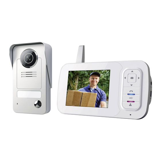
Indoor Monitor
1. Antenne
5. RIGHT button
9. Door lock button
2. Screen
6. OK / Photo button
10. Monitor button
3. UP button
7. DOWN button
11. Microphone
4. LEFT button
8. Intercom button
12. LED lighting
Installation and setup
Always test the product on site before installation.
Be aware that different materials in between the Outdoor Intercom
and Indoor Monitor will affect the operating performance of the product.
Follow the Wiring and pairing guides to test the product.
Install the Outdoor Intercom in a dry location if possible.
Mount the Intercom at a suitable height and position to allow the
camera to see the visitor
Battery setup:
Outdoors intercom
1. On the back of the intercom, remove the 6 screws on the battery
compartment, and remove the cover
2. Insert the battery pack into the compartment, making sure it is positioned
correctly, with the marking "Rechargeable Li-Ion battery" facing you.
3. Replace the battery compartment cover and insert the 6 screws.
Indoor Monitor
1. On the back of the indoor monitor, open the battery compartment
cover pulling towards you.
2. Insert the battery pack into the compartment, making sure it is positioned
correctly, with the marking "Rechargeable Li-Ion battery" facing you.
3. Replace the compartment cover.
Name plate
Name plate
1. If you need to fill the name plate, push strongly on the left side whilst
sliding the plate to the left in order to free the right side and then remove it.
2. Use a pointy object to remove the name plate from the inside of the
plate and fill-in your details.
3. Then, replace the label and follow the same steps in the opposite
order to reassemble the plate in the outdoor unit.
Included in the pack:
3
13
4
5
6
7
8
9
10
11
14
13. USB port
14. Power ON/OFF
15. Metal support screws
16. Metal supports
Outdoor intercom wall support
Inside
1. Select the location of the outdoor intercom, use the rain cover as a
template anD drill the holes to mount the plugs.
2. Mark and drill the hole in order to feed the electric cables through the wall.
3. Push the electric cables so that they are visible from the outside.
4. Glue the seal inside the rain cover.
Wiring
1. With a small screw driver, push the connexion bloc upwards on
the outdoor intercom in order to detach it.
2. Connect the DC power supply to the terminals marked + and -,
checking that the wires are linked correctly.
x2
17
18
15
16
17. Wall mount
18. Battery compartment cover
TOWARDS THE
17
Outdoors intercom
1. Rain cover
5. Speaker
2. Microphone
6. Name plate
3. Camera lens
7. Call button
4. Night vision lighting
8. Light sensor
Outside
1
2
3
5. Mount the rain cover with the mounting hardware included.
Pay attention to the mounting bracket on the lower support,
making sure the electric cables will fit through the joining
opening of the back plate in the lower corner.
6. Link the intercom electric cables as shown on the wiring diagram below.
7. Firstly, insert the upper part of the intercom into the rain cover and
place the lower part on the angled support.
8. Secure the intercom in place on the rain cover using the securing screws.
12V 1Amp MAX
T
OPTIONAL:
DOOR LOCK
OPTIONAL
3. If required, connect the door lock cables to the 2 terminals, checking
the correct power supply to the door lock (only for an electric door lock,
max. 12 V, 1 A , through a separate power plug - NOT INCLUDED).
4. Replace the connector in the outdoor intercom, making sure the
polarity is correct.
9
10
11
12
9. Antenne
10. Battery compartment
11. Screw
12. Power and locking connector
6
4
5
Advertisement
Table of Contents

Related Manuals for Smartwares VD38W


Summary of Contents for Smartwares VD38W
- Page 1 Included in the pack: CAUTION 1. Please read these instructions before setting up and using the device. 2. Do not cut the power supply cable to extend it; the transformer will not operate with a longer cable. Do not plug in the transformer until all the wiring has been finished. 3.
- Page 2 Only use recommended batteries. Complies to all relevant European directives. Remove the batteries if the device remains unused Smartwares declares the device, model [VD38W], complies for long periods. with the requirements of the R&TTE, 1999/5/CE directive. Keep the device away from small children.
Need help?
Do you have a question about the VD38W and is the answer not in the manual?
Questions and answers