Table of Contents
Advertisement
Advertisement
Table of Contents

Related Manuals for Wisenet XNF-9010RV


Summary of Contents for Wisenet XNF-9010RV
- Page 1 NETWORK CAMERA User Manual XNF-9010RV/XNF-9010RVM...
- Page 2 Network Camera User Manual Copyright ©2020 Co., Ltd. All rights reserved. Hanwha Techwin Trademark Each of trademarks herein is registered. The name of this product and other trademarks mentioned in this manual are the registered trademark of their respective company. Restriction Copyright of this document is reserved.
- Page 3 overview IMPORTANT SAFETY INSTRUCTIONS 23. This device has been verified using STP cable. The use of appropriate GND grounding and STP cable is recommended to effectively protect your product and property from transient voltage, thunderstroke, communication interruption. 1. Read these instructions. 2.
- Page 4 For below models only. Please use the input power with just one camera and other devices must not be connected. XNF-9010RV Before connecting the Power Terminal Block, you need to unplug the power plug from the outlet first.
-
Page 5: Table Of Contents
CONTENTS OVERVIEW WEB VIEWER Important Safety Instructions Connecting to the Camera Recommended PC Specifications Password setting Recommended Micro SD/SDHC/SDXC Login Memory Card Specifications Camera Web Viewer Setup NAS recommended specs What’s Included Optional Accessories for Installation At a Glance APPENDIX Troubleshooting INSTALLATION &... -
Page 6: Overview
overview RECOMMENDED PC SPECIFICATIONS NAS RECOMMENDED SPECS • CPU : Intel(R) Core(TM) i7 3.4 GHz or higher • Recommended capacity : 200GB or higher is recommended. • RAM : 8G or higher • For this camera, you are recommended to use a NAS with the following manufacturer’s specs. Recommended products : QNAP NAS, Synology NAS •... -
Page 7: What's Included
Quantity Description Model Name Appearance Item Name Quantity Description Model Name Extra cable bushing for network XNF-9010RV/ Cable bushing XNF-9010RV/ cable installation. XNF-9010RVM Camera XNF-9010RVM Used to supply power and connect M12 Female connector cable network when coupled with an M12... -
Page 8: Optional Accessories For Installation
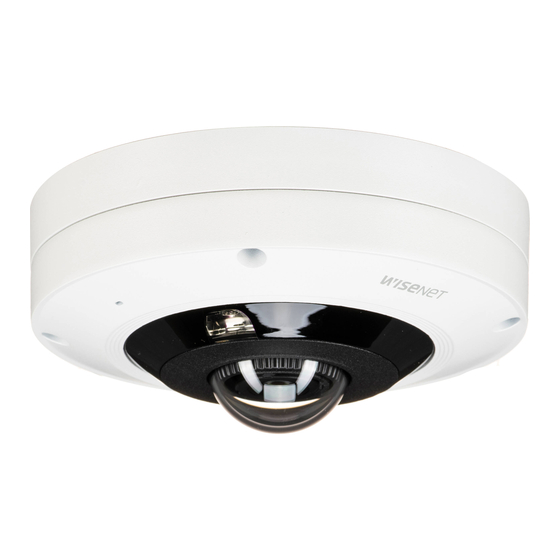
You can purchase appropriate optional accessories available. Appearance Model name Hanging Mount SBP-300LMW (Parapet Mount) SBP-300CMW (Ceiling Mount) SBP-300WMW (Wall Mount) SBP-300WMW1 (Wall Mount) XNF-9010RV/ SBP-167HMW XNF-9010RVM SBP-300NBW (Instalation Box) SBP-300NBW (Wall Mount Base) SBP-300PMW (Pole Mount) SBP-300KMW (Corner Mount) Item... - Page 9 Inside Item Description Network Port Used to connect the PoE or Ethernet cable for network connection. IR LED These infrared LED’s are controlled by the illumination sensor. Fisheye lens This lens has 360˚ vision and it can record video panoramically. Illumination Sensor Detects incoming light to control the IR LED.
-
Page 10: Installation & Connection
You don’t have to completely remove the screws. This camera(XNF-9010RV/XNF-9010RVM) is waterproof and in compliance with the IP66 spec, but the jack connected to the external cable is not. You are recommended to install this product below the edge of eaves to prevent the cable from being externally exposed. - Page 11 Removing a Micro SD card Installing the camera on the ceiling or a wall Gently press down on the exposed end of the Micro SD card as shown in the diagram to eject the Micro SD 1. Attach the installation template on the desired surface and drill holes for screws and cables. card from the slot.
- Page 12 installation & connection [Installing the network cable] [Installing the Audio/Alarm/Power cables] 4. Pull off the extruded parts of the cable bushing to be used. 7. Mount the cable bushing of the provided audio/alarm/power cables to the camera body. 5. Use the cap installer to route the network cable through the cable bushing. Cap Installer 6.
- Page 13 9. Connect the network cable and alarm/power, audio jack to the camera module port. 11. Assemble the top cover. TR20 When assembling the top cover, make the ‘FRONT’ mark on the camera body align with the logo on the cover. If the cover is not fixed tightly, you may encounter a problem with waterproofing.
- Page 14 installation & connection Adjusting the monitoring direction for the camera Installation precautions when using the IR Manual mode • This mode is recommended when the luminance from each direction is different when monitoring under low luminance. • Since the position of the IR LED is fixed, if you rotate the camera lens, only the monitoring video of the camera will rotate but not the irradiation direction of the IR LED.
-
Page 15: Connecting With Other Device
SOFT AP 1. Connect OTG adapter (5-pin) and WiFi dongle to the micro USB port. Smartphone Setup 1. Install the Wisenet Installation application. 2. Select the camera SSID after turning on the WiFi. 3. Run the Wisenet Installation application. 4. When you log in to the camera, the video will be connected. - Page 16 installation & connection Connecting a connector cable (XNF-9010RVM) Connecting to Audio Input/Output Connect the M12 male connector into the hole of the M12 Female connector of the camera. Speaker This camera uses Female, D-coded types. PoE (Power over Ethernet) is supported. You are recommended to use a shielded network connector.
- Page 17 Connecting to the I/O port box To connect the external sensor Connect the Alarm I/O cable to the corresponding port of the port box. Connect one of the 2 signal lines to the [ALARM #1] port (if you want this to be the input port) and the remaining one to the [GND] port.
-
Page 18: Network Connection And Setup
network connection and setup CONNECTING THE CAMERA DIRECTLY TO A DHCP BASED DSL/CABLE You can set up the network settings according to your network configurations. MODEM CONNECTING THE CAMERA DIRECTLY TO LOCAL AREA NETWORKING Connecting to the camera from a local PC in the LAN INTERNET 1. -
Page 19: Using Device Manager
USING DEVICE MANAGER If using a Broadband Router • IP Address : Enter an address falling in the IP range provided by the Broadband Router. Device manager program can be downloaded from <Technical Guides>-<Online Tool> menu at Hanwha Techwin website ex) 192.168.1.2~254, 192.168.0.2~254, (http://www.hanwha-security.com). -
Page 20: Manually Registering Camera
• Example of the Dynamic IP environment configure the IP. XNF-9010RV - If a Broadband Router, with cameras connected, is assigned an IP address by the DHCP server 2. Click < + > at the main page of device manager. -
Page 21: Port Range Forward (Port Mapping) Setup
Port forwarding can be done without additional router setup if the router supports the UPnP (Universal Plug and Play) function. For more information, refer to the user manual of the applicable router. After connecting the network camera, select the checkbox from the menu <Quick connect> in <Wisenet DDNS> in “Settings -> Network -> DDNS”. -
Page 22: Connecting To The Camera From A Shared Local Pc
2. From the remote PC, launch the Internet browser and type the DDNS URL address of the camera, or the IP address of the Broadband Router in the address bar. ex) http://ddns.hanwha-security.com/ID To use Wisenet DDNS, sign up at the Wisenet DDNS homepage (http://ddns.hanwha-security.com) and register the product at [My DDNS]>[Register Product]. 22_ network connection and setup... -
Page 23: Connecting To The Camera
To register your device to the <DDNS> server, visit http://ddns.hanwha-security.com and register your device 1. Launch the Internet browser. first, and then set the Web Viewer’s <Network> - <DDNS> to <Wisenet DDNS>, as well as providing <Product ID> that had been used for DDNS registration. -
Page 24: Password Setting
web viewer PASSWORD SETTING CAMERA WEB VIEWER SETUP When you access the product for the first time, you must register the Setup ( 1. Click the [ ] icon. login password. 2. The Settings window appears. 3. You can configure settings for the camera’s basic information, video, audio, network, event, analysis, and For a new password with 8 to 9 digits, you must use at least 3 of system over the network. -
Page 25: Troubleshooting
appendix TROUBLESHOOTING PROBLEM SOLUTION PROBLEM SOLUTION When an Windows 10 user accesses y If the transmission method is set to multicast, check whether there is a router that supports No image appears. y This is what happens when microphone driver has been set to Realtek driver. the web viewer through Chrome multicast in the LAN the camera is connected to. - Page 26 Any changes or modifications in construction of this device which are not expressly approved by the party responsible for compliance could void the user's authority to operate the equipment. This device complies with part 15 of the FCC Rules. Operation is subject to the following two conditions: (1) This device may not cause harmful interference, and (2) this device must accept any interference received, including interference that may cause undesired operation.
Need help?
Do you have a question about the XNF-9010RV and is the answer not in the manual?
Questions and answers