Advertisement
Quick Links
Version 1.0
Published July 2017
Copyright©2017 ASRock INC. All rights reserved.
Copyright Notice:
No part of this documentation may be reproduced, transcribed, transmitted, or
translated in any language, in any form or by any means, except duplication of
documentation by the purchaser for backup purpose, without written consent of
ASRock Inc.
Products and corporate names appearing in this documentation may or may not
be registered trademarks or copyrights of their respective companies, and are used
only for identification or explanation and to the owners' benefit, without intent to
infringe.
Disclaimer:
Specifications and information contained in this documentation are furnished for
informational use only and subject to change without notice, and should not be
constructed as a commitment by ASRock. ASRock assumes no responsibility for
any errors or omissions that may appear in this documentation.
With respect to the contents of this documentation, ASRock does not provide
warranty of any kind, either expressed or implied, including but not limited to
the implied warranties or conditions of merchantability or fitness for a particular
purpose.
In no event shall ASRock, its directors, officers, employees, or agents be liable for
any indirect, special, incidental, or consequential damages (including damages for
loss of profits, loss of business, loss of data, interruption of business and the like),
even if ASRock has been advised of the possibility of such damages arising from any
defect or error in the documentation or product.
This device complies with Part 15 of the FCC Rules. Operation is subject to the following
two conditions:
(1) this device may not cause harmful interference, and
(2) this device must accept any interference received, including interference that
may cause undesired operation.
CALIFORNIA, USA ONLY
The Lithium battery adopted on this motherboard contains Perchlorate, a toxic substance
controlled in Perchlorate Best Management Practices (BMP) regulations passed by the
California Legislature. When you discard the Lithium battery in California, USA, please
follow the related regulations in advance.
"Perchlorate Material-special handling may apply, see www.dtsc.ca.gov/hazardouswaste/
perchlorate"
ASRock Website: http://www.asrock.com
Advertisement

Related Manuals for ASROCK X299 Designer+


Summary of Contents for ASROCK X299 Designer+
- Page 1 (including damages for loss of profits, loss of business, loss of data, interruption of business and the like), even if ASRock has been advised of the possibility of such damages arising from any defect or error in the documentation or product.
- Page 2 If you require assistance please call ASRock Tel : +886-2-28965588 ext.123 (Standard International call charges apply)
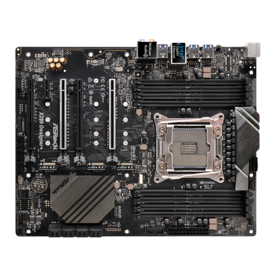
- Page 3 X299 Designer+ Motherboard Layout CPU_OPT/W_PUMP1 ATX12V1 CPU_FAN1 CLRC BTN1 2066 Socket USB 3.0 T: USB3 B: USB4 USB 3.0 T: USB1 B: USB2 USB 2.0 Top: T: USB1 RJ-45 B: USB2 USB 3.1 T: USB31_TA_1 B: USB31_TC_1 CHA_FAN2 VROC1 PCIE1 RoHS Intel X299...
- Page 4 No. Description 2 x 288-pin DDR4 DIMM Slots (DDR4_A1, DDR4_B1) 2 x 288-pin DDR4 DIMM Slots (DDR4_A2, DDR4_B2) ATX 12V Power Connector (ATX12V1) CPU Fan / Waterpump Fan Connector (CPU_OPT/W_PUMP1) 2 x 288-pin DDR4 DIMM Slots (DDR4_C2, DDR4_D2) 2 x 288-pin DDR4 DIMM Slots (DDR4_C1, DDR4_D1) CPU Fan Connector (CPU_FAN1) ATX Power Connector (ATXPWR1) Virtual RAID On CPU Header (VROC1)
- Page 5 X299 Designer+ I/O Panel No. Description No. Description USB 2.0 Port (USB_3_4) USB 3.1 Type-A Port (USB31_TA_1) LAN RJ-45 Port (Intel® I219V)* USB 3.1 Type-C Port (USB31_TC_1) Central / Bass (Orange) USB 2.0 Ports (USB_1_2) Rear Speaker (Black) USB 3.0 Ports (USB3_1_2) Line In (Light Blue) USB 3.0 Ports (USB3_3_4) Front Speaker (Lime)**...
- Page 6 ** If you use a 2-channel speaker, please connect the speaker’s plug into “Front Speaker Jack”. See the table below for connection details in accordance with the type of speaker you use. Audio Output Front Speaker Rear Speaker Central / Bass Line In Channels (No.
- Page 7 If you require technical support related to this mother- board, please visit our website for specific information about the model you are using. You may find the latest VGA cards and CPU support list on ASRock’s website as well. ASRock website http://www.asrock.com.
- Page 8 933(OC)/2800(OC)/2666/2400/2133 non-ECC, un-buffered memory * The maximum memory frequency supported may vary by processor type. * Please refer to Memory Support List on ASRock’s website for more information. (http://www.asrock.com/) • Supports non-ECC RDIMM (Registered DIMM) • Max. capacity of system memory: 128GB • Supports Intel®...
- Page 9 X299 Designer+ ** If PCIE4 slot is occupied, M2_2 slot will support M.2 PCI Express module up to Gen3 x2 (16 Gb/s). • Supports AMD Quad CrossFireX , 3-Way CrossFireX and CrossFireX • Supports NVIDIA® Quad SLI , 3-Way SLI and SLI *** 3-Way CrossFireX and 3-Way SLI...
- Page 10 Express module up to Gen3 x2 (16 Gb/s). ** Supports Intel® Optane Technology ** Supports NVMe SSD as boot disks ** Supports ASRock U.2 Kit • 1 x Virtual RAID On CPU Header Connector • 1 x TPM Header • 1 x Power LED and Speaker Header • 1 x CPU Fan Connector (4-pin)
- Page 11 X299 Designer+ • 1 x CPU Optional/Water Pump Fan Connector (4-pin) * The CPU Optional/Water Pump Fan supports the water cooler fan of maximum 1.5A (18W) fan power. • 2 x Chassis Fan Connectors (4-pin) (Smart Fan Speed Con- trol) • 1 x Chassis Optional/Water Pump Fan Connector (4-pin) * The Chassis Optional/Water Pump Fan supports the water cooler fan of maximum 1.5A (18W) fan power.
- Page 12 • ErP/EuP ready (ErP/EuP ready power supply is required) * For detailed product information, please visit our website: http://www.asrock.com Please realize that there is a certain risk involved with overclocking, including adjusting the setting in the BIOS, applying Untied Overclocking Technology, or using third-party overclocking tools.
- Page 13 X299 Designer+ 1.3 ASRock Thunderbolt 3 AIC Installation Guide Card Layout No. Description Thunderbolt 3 Type-C Port Thunderbolt 3 Type-C Port DisplayPort IN Port Mini DisplayPort IN Port PCI Express 3.0 Interface TBT Header...
- Page 14 Specifications Platform • Dimensions: 3.3-in x 4.1-in Chipset • Intel® JHL6540 Thunderbolt™ 3 Controller External • 2 x Thunderbolt™ 3 Type-C Ports (with up to Connectors 40Gbps bandwidth) * Supports daisy-chaining of up to six Thunderbolt™ devices • 1 x DisplayPort IN Port • 1 x Mini DisplayPort IN Port • 1 x TBT Header Interface...
- Page 15 X299 Designer+ 1 Installing the Thunderbolt 3 AIC 1. Power off the PC and unplug the power cord. Detach all other cables from the PC. 2. Remove the PC cover. 3. Align and insert the card into a PCI Express 3.0 slot on the motherboard. Press firmly until the card is securely seated in place.
- Page 16 5. Connect one end of the DisplayPort Cable to the DisplayPort IN Port (A) on the Thunderbolt 3 AIC. Then connect the other end of the cable to the DisplayPort Port (B) on your graphics card. DisplayPort Cable 6. Connect one end of the Mini DisplayPort to DisplayPort Adapter Cable to the Mini DisplayPort Port (A) on the Thunderbolt 3 AIC.
- Page 17 X299 Designer+ 7. Replace the PC cover. 8. Reconnect the power cord and any other cables that were disconnected. Then power on the PC. 2 Connecting the Thunderbolt™ Cable Connect the Thunderbolt cable from your Thunderbolt-enabled device to the Thunderbolt 3 Port on the Thunderbolt 3 AIC.
- Page 18 3 Enabling the Thunderbolt™ Function After hardware installation is completed, enter the BIOS Setup and enable the Intel® Thunderbolt™ function in BIOS setup. 4 Installing the Thunderbolt Software in Windows Place the Support CD into your CD-ROM drive and follow the on-screen instructions to complete the installation.
- Page 19 SAS SSD package. Step 2 Align and gently install the ASRock U.2 Kit into the M.2 Socket on the motherboard. *Please be aware that the ASRock U.2 Kit only fits in one orientation. Then tighten the screw to secure it into place.
- Page 20 Chapter 2 Installation This is an ATX form factor motherboard. Before you install the motherboard, study the configuration of your chassis to ensure that the motherboard fits into it. Pre-installation Precautions Take note of the following precautions before you install motherboard components or change any motherboard settings.
- Page 21 X299 Designer+ 2.1 Installing the CPU 1. Before you insert the 2066-Pin CPU into the socket, please check if the PnP cap is on the socket, if the CPU surface is unclean, or if there are any bent pins in the socket. Do not force to insert the CPU into the socket if above situation is found.
- Page 23 X299 Designer+ Please save and replace the cover if the processor is removed. The cover must be placed if you wish to return the motherboard for after service.
- Page 24 2.2 Installing the CPU Fan and Heatsink...
- Page 25 X299 Designer+ 2.3 Installation of Memory Modules (DIMM) This motherboard provides eight 288-pin DDR4 (Double Data Rate 4) DIMM slots, and supports Quad Channel Memory Technology. 1. For quad channel configuration, you always need to install identical (the same brand, speed, size and chip-type) DDR4 DIMM pairs.
- Page 26 • For CPU with 16 PCIe lanes, please install the memory modules on DDR4_C1, C2, D1 and D2 only.
- Page 27 X299 Designer+ 2.4 Expansion Slots (PCI Express Slots) There are 5 PCI Express slots on the motherboard. Before installing an expansion card, please make sure that the power supply is switched off or the power cord is unplugged. Please read the documentation of the expansion card and make necessary hardware settings for the card before you start the installation.
- Page 28 PCIe Slot Configurations (For CPU with 28 PCIe lanes) PCIE1 PCIE2 PCIE3 PCIE4 PCIE5 Single Graphics Card Two Graphics Cards in CrossFireX or SLI Mode PCIe Slot Configurations (For CPU with 16 PCIe lanes) PCIE1 PCIE2 PCIE3 PCIE4 PCIE5 Single Graphics Card Two Graphics Cards in CrossFireX or SLI...
- Page 29 X299 Designer+ 2.5 Jumpers Setup The illustration shows how jumpers are setup. When the jumper cap is placed on the pins, the jumper is “Short”. If no jumper cap is placed on the pins, the jumper is “Open”. The illustration shows a 3-pin jumper whose pin1 and pin2 are “Short” when a jumper cap is placed on these 2 pins.
- Page 30 2.6 Onboard Headers and Connectors Onboard headers and connectors are NOT jumpers. Do NOT place jumper caps over these headers and connectors. Placing jumper caps over the headers and connectors will cause permanent damage to the motherboard. System Panel Header Connect the power PLED+ PLED-...
- Page 31 X299 Designer+ Power LED and Speaker Please connect the SPEAKER DUMMY Header chassis power LED and DUMMY (7-pin SPK_PLED1) the chassis speaker to this (see p.1, No. 15) header. PLED+ PLED+ PLED- Serial ATA3 Connectors These eight SATA3 (SATA3_0_1: connectors support SATA see p.1, No.
- Page 32 USB 3.0 Header There is one header on Vbus Vbus Vbus IntA_PB_SSRX- (19-pin USB3_5_6) this motherboard. This IntA_PA_SSRX- IntA_PB_SSRX+ IntA_PA_SSRX+ (see p.1, No. 10) USB 3.0 header can IntA_PB_SSTX- IntA_PA_SSTX- IntA_PB_SSTX+ support two ports. IntA_PA_SSTX+ IntA_PB_D- IntA_PA_D- IntA_PB_D+ IntA_PA_D+ Dummy Front Panel Audio Header This header is for PRESENCE#...
- Page 33 X299 Designer+ (4-pin CHA_FAN2) (see p.1, No. 26) FAN_SPEED_CONTROL CHA_FAN_SPEED FAN_VOLTAGE Chassis Optional/Water This motherboard Pump Fan Connector provides two 4-Pin water (4-pin CHA_FAN3/W_ cooling chassis fan FAN_SPEED_CONTROL CHA_FAN_SPEED PUMP2) connectors. If you plan to FAN_VOLTAGE (see p.1, No. 18) connect a 3-Pin chassis water cooler fan, please connect it to Pin 1-3.
- Page 34 ATX 12V Power This motherboard Connector provides an 8-pin ATX (8-pin ATX12V1) 12V power connector. To (see p.1, No. 3) use a 4-pin ATX power supply, please plug it along Pin 1 and Pin 5. TPM Header This connector supports Trusted (17-pin TPMS1) Platform Module (TPM) system, (see p.1, No.
- Page 35 X299 Designer+ With the introduction of the Intel VROC product, there are three modes of operation: HW key required Key features • Pass-thru only (no RAID) • LED Management Pass-thru Not needed • Hot Plug Support • RAID 0 support for Intel Fultondale NVMe SSDs • Pass-thru SKU features Standard VROCSTANMOD...
- Page 36 2.7 Smart Switches The motherboard has a smart switch: Clear CMOS Switch, allowing users to clear the CMOS values. Clear CMOS Switch Clear CMOS Switch (CLRCBTN) allows users to quickly (see p.3, No. 14) clear the CMOS values. This function is workable only when you power off your computer and unplug the power supply.
- Page 37 X299 Designer+ 2.8 M.2_SSD (NGFF) Module Installation Guide The M.2, also known as the Next Generation Form Factor (NGFF), is a small size and versatile card edge connector that aims to replace mPCIe and mSATA. The Ultra M.2 Socket can accommodate either a M.2 SATA3 6.0 Gb/s module or a M.2 PCI Express module up to Gen3 x4 (32 Gb/s).
- Page 38 Step 3 Move the standoff based on the module type and length. The standoff is placed at the nut location D by default. Skip Step 3 and 4 and go straight to Step 5 if you are going to use the default nut. Otherwise, release the standoff by hand.
- Page 39 X299 Designer+ M.2_SSD (NGFF) Module Support List Vendor Interface ADATA SATA3 AXNS330E-32GM-B ADATA SATA3 AXNS381E-128GM-B ADATA SATA3 AXNS381E-256GM-B ADATA SATA3 ASU800NS38-256GT-C ADATA SATA3 ASU800NS38-512GT-C ADATA PCIe3 x4 ASX8000NP-256GM-C ADATA PCIe3 x4 ASX8000NP-512GM-C Crucial SATA3 CT120M500SSD4 Crucial SATA3 CT240M500SSD4 Intel SATA3 Intel SSDSCKGW080A401/80G Intel PCIe3 x4...
- Page 40 SATA3 WDS100T1B0B-00AS40 SATA3 WDS240G1G0B-00RC30 PCIe3 x4 WDS256G1X0C-00ENX0 (NVME) PCIe3 x4 WDS512G1X0C-00ENX0 (NVME) For the latest updates of M.2_SSD (NFGG) module support list, please visit our website for details: http://www.asrock.com...
- Page 41 产的性能可靠的主板。它提供符合华擎质量和耐久性承诺的精良设计和卓越性 能。 由于主板规格和 BIOS 软件可能已更新,因此,本文档的内容可能会随时更改,恕不 另行通知。如果本文档有任何修改,则更新的版本将发布在华擎网站上,我们不会另 外进行通知。如果您需要与此主板相关的技术支持,请访问我们的网站以具体了解所 用型号的信息。您也可以在华擎网站上找到最新 VGA 卡和 CPU 支持列表。华擎网站 http://www.asrock.com。 1.1 包装清单 • 华擎 X299 Designer+ 主板(ATX 规格尺寸) • 华擎 X299 Designer+ 快速安装指南 • 华擎 X299 Designer+ 支持光盘 • 1 x I/O 面板 • 1 x 华擎 SLI_HB_Bridge_2S 卡(选购)...
- Page 42 • 支持 DDR4 4400+(OC)*/4266(OC)/4133(OC)/4000(OC)/3866 (OC)/3800(OC)/3733(OC)/3600(OC)/3200(OC)/2933(OC)/2800 (OC)/2666/2400/2133 非 ECC,非缓冲内存 * 支持的最大内存频率可能根据处理器类型而变化。 * 请参阅华擎网站上的 Memory Support List(内存支持列表)了 解详情。(http://www.asrock.com/) • 支持非 ECC RDIMM(寄存型 DIMM) • 支持系统内存最大容量: 128GB • 支持 Intel® Extreme Memory Profile (XMP) 2.0 • DIMM 插槽中 15μ 金触点 • 4 x PCI Express 3.0 x16 槽 * 扩充槽...
- Page 43 X299 Designer+ • 具有内容保护功能的 7.1 CH 高清音频(Realtek ALC1220 音 音频 频编解码器) • 优质 Blu-ray 音频支持 • 支持电涌保护 • 支持 Purity Sound - Nichicon Fine Gold 系列音频电容 - 120dB SNR DAC,带微分放大器 - 用于前面板音频接口的 TI® NE5532 高品质耳机放大器(支 持最高 600 Ohm 耳机) - 纯电源输入 - Direct Drive(直接驱动)技术...
- Page 44 • 8 x SATA3 6.0 Gb/s 接口,支持 RAID(RAID 0、RAID 1、 存储 RAID 5、RAID 10、Intel Rapid Storage Technology 15 和 Intel Smart Response Technology)、NCQ、AHCI 和热插拔 * 如果 M2_1 被 SATA 型 M.2 设备占用,SATA3_0 将被禁用。 * 如果 M2_2 被 SATA 型 M.2 设备占用,SATA3_1 将被禁用。 * 如果...
- Page 45 CPU 可选 / 水泵、机箱、机箱可选 / 水泵风扇 • 风扇多种速度控制 : CPU、CPU 可选 / 水泵、机箱、机箱可 选 / 水泵风扇 • 电压监控: +12V、+5V、+3.3V、CPU Vcore、DRAM、PCH 1.0V、VCCIO、VCCSA、VCCSFR • Microsoft® Windows® 10 64-bit 操作系统 • FCC、CE 认证 • ErP/EuP 支持(需要支持 ErP/EuP 的电源) * 有关详细产品信息,请访问我们的网站: http://www.asrock.com 须认识到超频会有一定风险,包括调整 BIOS 设置,应用“自由超频技术”,或使用第 三方超频工具。超频可能会影响到系统的稳定性,甚至对系统的组件和设备造成损坏。 执行这项工作您应自担风险和自己承担费用。我们对由于超频而造成的损坏概不负责。...
- Page 46 1.3 跳线设置 此图显示如何设置跳线。将跳线帽装到这些针脚上时,跳线 “短接”。如果这 些针脚上没有装跳线帽,跳线 “开路”。此图显示 3 针跳线,当跳线帽装在针 脚 1 和针脚 2 上,它们“短接”。 清除 CMOS 跳线 (CLRMOS1) 清除 CMOS ( 见第 1 页,第 24 个) 默认 CLRMOS1 允许您清除 CMOS 中的数据。要清除和重置系统参数到默认设 置,请关闭计算机,从电源上拔下电源线插头。等候 15 秒后,使用跳线帽将 CLRMOS1 上的针脚 2 和针脚 3 短接 5 秒。但是,请勿在更新 BIOS 后立即清 除...
- Page 47 X299 Designer+ 1.4 板载接脚和接口 板载接脚和接口不是跳线。不要将跳线帽装到这些接脚和接口上。将跳线帽装到这些 接脚和接口上将会对主板造成永久性损坏。 系统面板接脚 按照下面的针脚分配, PLED+ PLED- (9 针 PANEL1) PWRBTN# 将机箱上的电源开关、 ( 见第 1 页,第 17 个 ) 重置开关和系统状态指 示灯连接到此接脚。在 RESET# 连接线缆前请记下正负 HDLED- 针脚。 HDLED+ PWRBTN(电源开关): 连接到机箱前面板上的电源开关。您可以配置使用电源开关关闭系统的方式。 RESET(重置开关): 连接到机箱前面板上的重置开关。如果计算机死机,无法执行正常重新启动,按重置 开关重新启动计算机。 PLED(系统电源 LED): 连接到机箱前面板上的电源状态指示灯。系统操作操作时,此 LED 亮起。系统处在 S1/S3 睡眠状态时,此 LED 闪烁。系统处在 S4 睡眠状态或关机 (S5) 时,此 LED 熄灭。 HDLED(硬盘活动...
- Page 48 电源 LED 和扬声器接脚 请将机箱电源 LED 和机 SPEAKER DUMMY (7 针 SPK_PLED1) 箱扬声器连接到此接脚。 DUMMY ( 见第 1 页,第 15 个 ) PLED+ PLED+ PLED- 串行 ATA3 接口 这八个 SATA3 接口支持 (SATA3_0_1: 最高 6.0 Gb/s 数据传输 见第 1 页,第 11 个 ) 速率的内部存储设备的...
- Page 49 X299 Designer+ USB 3.0 接脚 此主板上有一个接 Vbus Vbus Vbus IntA_PB_SSRX- (19 针 USB3_5_6) 脚。此 USB 3.0 接脚 IntA_PA_SSRX- IntA_PB_SSRX+ IntA_PA_SSRX+ ( 见第 1 页,第 10 个 ) 支持两个端口。 IntA_PB_SSTX- IntA_PA_SSTX- IntA_PB_SSTX+ IntA_PA_SSTX+ IntA_PB_D- IntA_PA_D- IntA_PB_D+ IntA_PA_D+ Dummy 前面板音频接脚 此接脚用于将音频设 PRESENCE# MIC_RET (9 针...
- Page 50 (4 针 CHA_FAN2) ( 见第 1 页,第 26 个 ) FAN_SPEED_CONTROL CHA_FAN_SPEED FAN_VOLTAGE 机箱可选 / 水泵风扇接口 此主板提供两个 4 针 水冷机箱风扇接口 (4 针 CHA_FAN3/W_ PUMP2) FAN_SPEED_CONTROL 如果您打算连接 3 针 CHA_FAN_SPEED ( 见第 1 页,第 18 个 ) FAN_VOLTAGE 机箱水冷风扇,请将 它连接到针脚 1-3。 CPU 风扇接口...
- Page 51 X299 Designer+ ATX 12V 电源接口 此主板提供 8 针 ATX (8 针 ATX12V1) 12V 电源接口。要使用 4 ( 见第 1 页,第 3 个 ) 针 ATX 电源,请沿针脚 1 和针脚 5 插接它。 TPM 接脚 此接口支持 Trusted Platform (17 针 TPMS1) Module(信任平台模块, ( 见第 1 页,第 22 个 ) TPM)系统,可以安全地存储...
- Page 52 Intel VCOR 产品推出后的三种操作模式: 需要硬件按键 主要功能 • 仅 Pass-thru (不支持 RAID) • LED 指示灯管理 Pass-thru • 支持热插拔 不需要 • 支持使用 Intel Fultondale NVMe 固态硬盘创建 RAID 0 • Pass-thru SKU 的功能 VROCSTANMOD 标准 • RAID 0, 1, 10 VROCPREMMOD 优质 • 标准 SKU 的功能 • RAID 5 • RAID 5 Write Hole 闭合...
- Page 53 X299 Designer+ 1.5 智能开关 此主板配有 1 个智能开关: 清除 CMOS 开关允许用户清除 CMOS 值。 清除 CMOS 开关 清除 CMOS 开关允许用 (CLRCBTN) 户快速清除 CMOS 值。 ( 见第 3 页,第 14 个 ) 只有在关闭计算机并拔下电源插头后,才能使用此功能。...
- Page 54 电子信息产品污染控制标示 依据中国发布的「电子信息产品污染控制管理办法」及 SJ/T 11364-2006「电子 信息产品污染控制标示要求」,电子信息产品应进行标示,藉以向消费者揭露 产品中含有的有毒有害物质或元素不致发生外泄或突变从而对环境造成污染或 对人身、财产造成严重损害的期限。依上述规定,您可于本产品之印刷电路板 上看见图一之标示。图一中之数字为产品之环保使用期限。由此可知此主板之 环保使用期限为 10 年。 图一 有毒有害物质或元素的名称及含量说明 若您欲了解此产品的有毒有害物质或元素的名称及含量说明,请参照以下表格 及说明。 有害物质或元素 部件名称 铅 (Pb) 镉 (Cd) 汞 (Hg) 六价铬 (Cr(VI)) 多溴联苯 (PBB) 多溴二苯醚 (PBDE) 印刷电路板 及电子组件 外部信号连 接头及线材 O: 表示该有毒有害物质在该部件所有均质材料中的含量均在 SJ/T 11363-2006 标准规定 的限量要求以下。 X: 表示该有毒有害物质至少在该部件的某一均质材料中的含量超出 SJ/T 11363-2006 标准 规定的限量要求,然该部件仍符合欧盟指令...
- Page 55 X299 Designer+ UEFI SETUP UTILITY 1 简介 本节介绍如何使用 UEFI SETUP UTILITY 配置您的系统。打开计算机电源后 按 <F2> 或 <Del> ,您可以运行 UEFI SETUP UTILITY ,否则,开机自检 (POST) 将继续其测试例程。如果您想要在 POST 后进入 UEFI SETUP UTILITY , 可按 <Ctl> + <Alt> + <Delete> 或按系统机箱上的重置按钮重新启动系统。也可以通过 关闭系统后再开启来重新启动它 。 由于 UEFI 软件在不断更新,因此以下 UEFI 设置屏幕和说明仅供参考,并且可能 与您在自己屏幕上看到的内容不同。...
- Page 56 2 EZ 模式 默认情况下 ,进入 BIOS 设置程序时,EZ Mode ( EZ 模式) 屏幕会出现。 EZ 模式 是一个仪表盘, 包含系统当前状态的多个读数 。 您可以检查系统最重要的信息 , 如 : CPU 速度、DRAM 频率、SATA 信息 、 风扇速度等。 按 <F6> 或单击屏幕右上角的 “Advanced Mode ( 高级模式) ” 按钮可以切换到 “高 级模式” ,访问更多选项。 编号 功能...
- Page 57 X299 Designer+ 3 高级模式 高级模式提供更多选项来配置 BIOS 设置。 请参阅以下部分了解详细配置。 要访问 EZ 模式 ,请按 <F6> 或单击屏幕右上角的 “EZ Mode (EZ 模式 )” 按钮。 3.1 UEFI 菜单栏 屏幕上部有一个菜单栏包含以下选项 : 设置系统时间 / 日期信息 主画面 超频工具 超频配置 高级系统配置 高级 工具 有用的工具 硬件监視器 显示当前硬件状态 引导 配置引导设置和引导优先级 安全 安全设置...
- Page 58 3.2 导航键 使用 < > 键或 < > 键选择菜单栏上的选项,并使用 < > 键或 < > 键上下 移动光标以选择项目 ,然后按 <Enter> 进入子屏幕。您也可以使用鼠标单击需要 的项目 。 请检查下表了解每个导航键的说明。 导航键 说明 + / - 更改所选项目的选项 <Tab> 切换到下一个功能 <PGUP> 转到上一页 <PGDN> 转到下一页 <HOME> 转到屏幕顶部 <END> 转到屏幕底部 <F1> 显示一般帮助屏幕 <F7>...
- Page 59 X299 Designer+ 4 主画面 在您进入 UEFI SETUP UTILITY 时, 主画面会出现并显示系统概览 。 定制型 UEFI 显示您所收藏的 BIOS 项目 。按下 <F5> 可添加 / 移除收藏的项目 。...
- Page 60 5 超频工具 在超频工具屏幕中,您可以设置超频功能。 由于 UEFI 软件在不断更新,因此以下 UEFI 设置屏幕和说明仅供参考,并且可能 与您在自己屏幕上看到的内容不同。 Advanced Turbo 您可使用此选项增加您的系統性能。此选项只在您的 CPU 支持此功能时出现。 只在采用 K-Series CPU 时此选项出现。 加载优化 CPU OC 设置 您可以使用此选项加载优化的 CPU 超频设置。 请注意,超频可能会损坏 CPU 和 主板。 执行这项工作您应自担风险和自己承担费用。 只在采用 K-Series CPU 时 此选项出现。...
- Page 61 X299 Designer+ CPU 配置 All Core Ratio (全部内核倍频) CPU 核心运行的最大核心倍频。 Per Core Mode (每个内核模式) 默认情况下 ,每个内核模式禁用。 CPU Mesh Max OC Ratio (CPU Mesh 最大 OC 倍频) 为 CPU Mesh 设置最大超频倍频。 CPU Mesh Max OC Ratio (CPU Mesh 最大 OC 倍频) 为...
- Page 62 MFC Mode Override (MFC 模式超驰) 配置 MFC 模式超驰。 Adjust Pll ( 调整 Pll) 调整 Pll 以获得更高 -BCLK 比率组合。 Pll Trim (Pll 微调) 在 +63 到 -63 之间调整 Pll 值。 Pll Trim Prefix (Pll 微调前缀) 调整 Pll 微调前缀。 Change MC-Pll Trim Value (内存控制器的 Pll 微调) 在...
- Page 63 X299 Designer+ Primary Plane Current Limit ( 第一平台电流限制) 配置 Turbo 模式下 CPU 的电流限制 (安培) 较低限制可保护 CPU 和节能,较高限制可 提高性能。 Long Duration Power Limit ( 长持续时间功率限制) 配置封装功率限制 1 (瓦) 超过此限制时,一段时间后 CPU 倍频将降低。较低限制可保 护 CPU 和节能,较高限制可提高性能。 Long Duration Maintained (维持的长持续时间) 当超过长持续时间功率限制、 直到 CPU 倍频降低时配置一段时间。 Short Duration Power Limit (...
- Page 64 Row Precharge (tRP) ( 列预充电) Row Precharge (列预充电) : 发出 precharge (预充电) 命令到打开下一行之间需要的时 钟周期数。 RAS# Active Time (tRAS) ( 行地址动态时间) bank active 命令与发出 precharge (预充电) 命令之间需要的时钟周期数。 Command Rate (CR) ( 命令速率) 选择内存芯片和可以发出第一个 active 命令之间的延迟。 Secondary Timing (次时序) Write Recovery Time (tWR) ( 写入恢复时间) 在完成有效写入操作之后,...
- Page 65 X299 Designer+ Third Timing (第三时序) tREFI 配置平均周期间隔时间的刷新周期。 tCKE 配置 DDR4 进入自刷新模式后从内部开始执行至少一个刷新命令的时段。 tCCD 配置同一个等级分隔 ( rank separation ) 参数的后 - 后 CAS 至 CAS (即: READ 至 RAED 或 WRITE 至 WRITE ) 。 tCCD_L 配置同一个等级分隔 ( rank separation ) 参数的后 - 后 CAS 至 CAS (即: READ 至 RAED 或...
- Page 66 tWRDS 使用此项目更改 tWRDS 设置。默认值是 [Auto] ( 自动) 。 tWRDR 使用此项目更改 tWRDR 设置。默认值是 [Auto] ( 自动) 。 tWRDD 使用此项目更改 tWRDD 设置。默认值是 [Auto] ( 自动) 。 tWWDS 使用此项目更改 tWWDS 设置。默认值是 [Auto] ( 自动) 。 tWWDR 使用此项目更改 tWWDR 设置。默认值是 [Auto] ( 自动) tWWDD 使用此项目更改...
- Page 67 X299 Designer+ RTL (D2) ( 往返延迟 (D2) ) 设置通道 D2 的往返延迟。 IOL (A1) (IO 延迟 (A1) ) 设置通道 A1 的 IO 延迟。 IOL (A2) ( IO 延迟 (A2) ) 设置通道 A2 的 IO 延迟。 IOL (B1) ( IO 延迟 (B1) ) 设置通道...
- Page 68 ODT WR (C1) 配置通道 C1 的内存终结电阻器 WR 。 ODT WR (C2) 配置通道 C2 的内存终结电阻器 WR 。 ODT WR (D1) 配置通道 D1 的内存终结电阻器 WR 。 ODT WR (D2) 配置通道 D2 的内存终结电阻器 WR 。 ODT PARK (A1) 配置通道 A1 的内存终结电阻器 PARK 。 ODT PARK (A2) 配置通道...
- Page 69 X299 Designer+ ODT NOM (C1) 使用此项目更改 ODT (C1) 为自动 / 手动设置。默认设置为 【自动】 。 ODT NOM (C2) 使用此项目更改 ODT (C2) 为自动 / 手动设置。默认设置为 【自动】 。 ODT NOM D1) 使用此项目更改 ODT (D1) 为自动 / 手动设置。默认设置为 【自动】 。 ODT NOM (D2) 使用此项目更改 ODT (D2) 为自动 / 手动设置。默认设置为 【自动】 。 MRC Promote Warnings (MRC 提升警告)...
- Page 70 VPPM CD Voltage (VPPM CD 电压) 配置 VPPM CD 电压。 DRAM CD Voltage (DRAM CD 电压) 配置 DRAM CD 电压。 VTTM CD Voltage (VTTM CD 电压) 配置 VTTM CD 电压。 1.0V PCH Voltage (1.0V PCH 电压) 配置芯片电压 (1.0V) 。 PCH PLL Voltage (PCH PLL 电压) PCH PLL 电压有助于...
- Page 71 X299 Designer+ CPU Mesh Voltage Offset ( CPU Mesh 电压偏移) 设置 CPU Mesh 的偏移电压。 此电压单位为 “毫伏” 。 Offset Prefix (偏移前缀) 设置偏移值为正数或负数。 Sysyem Agent Voltage Offset ( 系统代理电压偏移) 设置系统代理的偏移电压。 此电压单位为 “毫伏” 。 Offset Prefix (偏移前缀) 设置偏移值为正数或负数。 VCCU Voltage Offset ( VCCU 电压偏移) 设置...
- Page 72 6 高级 在此部分中,您可以配置以下项目 : CPU 配置、芯片组配置、存储配置、Intel (R) Thunderbolt 、超级 IO 配置、 ACPI 配置、USB 配置和可信赖运算 。 在此部分中设置错误的值可能会造成系统故障。 UEFI 设置 UEFI 设置样式 选择进入 UEFI 设置实用程序时的设置样式 。 初始页面 选择进入 UEFI 设置实用程序时的默认页面。 高清 UEFI 当设置为 [ 自动 ] 时,若显示器支持全高清分辨率,则 UEFI 显示分辨率将为 1920 x 1080。若显示器不支持全高清分辨率,则 UEFI 显示分辨率为 1024 x 768。当设 置为...
- Page 73 X299 Designer+ 6.1 CPU 配置 Intel 超线程技术 Intel 超线程技术允许在每个内核上运行多个线程, 从而提升线程软件的整体性能。 激活处理器内核 选择在每个处理器封装中启用的内核数。 CPU C 状态支持 启用 CPU C 状态支持以节能。建议将 C3、C6 和 C7 全都启用以达到更好节能目 的。 Processor Hot Modes (处理器散热模式) 当处理器热量感应启动时 (或核心) ,PROCHOT# 将会被驱动。若双向模式开启, 外部代理可以驱动 PROCHOT# 以调节处理器。 CPU 过热降频保护 启用 CPU 内部温度控制以防 CPU 过热。 Intel 虚拟化技术...
- Page 74 Intel Safer Mode Extensions (SMX) 启用 / 禁用 Intel SMX (Safer Mode Extensions)。 硬件预取器 自动预取处理器的数据和代码。启用可取得更多性能。 相邻缓存行预取 在检索当前请求缓存行的同时预取后面缓存行。启用可取得更多性能。...
- Page 75 X299 Designer+ 6.2 芯片组配置 Above 4GB MMIO BIOS Assignment 启用 / 禁用 4GB 以上的 MemoryMappedIO BIOS 分配。在 Aperture Size (孔径大小) 设 置为 2048MB 时自动禁用。 VT-d Intel® 虚拟化技术 Directed I/O 支持可帮助您的虚拟机监视器通过提高应用程序 兼容性和可靠性, 以及提供额外的可管理性、安全性、隔离和 I/O 性能,来更好地 利用硬件。 PCIE1 连接速度 选择 PCIE1 连接速度。 PCIE2 连接速度...
- Page 76 PCI Express 原生控制 选择开启可提升 PCI Express 在操作系统中的节能性能。 PCI-E ASPM 支持 此选项启用 / 禁用针对所有 CPU 下游设备的 ASPM 支持 PCH PCI-E ASPM 支持 此选项启用 / 禁用针对所有 PCH 下游设备的 ASPM 支持 PCH DMI ASPM 支持 此选项启用 / 禁用所有 PCH DMI 设备的 ASPM 支持。 板载...
- Page 77 X299 Designer+ 6.3 存储配置 SATA 控制器 启用 / 禁用 SATA 控制器。 SATA 控制器速度 指示 SATA 控制器可支持的最大速度。 SATA 模式选择 [ AHCI ] : 支持可提升性能的新功能。 [ RAID ] : 将多个磁盘驱动器合并到一个逻辑单元。 替换 ID 替换 ID 项目允许您开启或关闭替换设备 ID 的报告功能。 [ 开启 ]: 开启 RSTe (Rapid Storage Technology enterprise) 功能。 [ 关闭...
- Page 78 SATA 主动式链接电源管理 允许 SATA 设备在不活动期间进入低能耗以达到节能目的。仅 AHCI 模式支持。 硬盘 S.M.A.R.T. S.M.A.R.T 表示自我监控、分析和报告技术。它是计算机硬盘的监控系统, 用来检 测和报告不同的可行性指标。...
- Page 79 X299 Designer+ 6.4 Intel (R) Thunderbolt Intel Thunderbolt 技术 开启或关闭 Intel® Thunderbolt 功能。 安全级别 您可以为 Thunderbolt 端口选择安全级别...
- Page 80 6.5 超级 IO 配置 PS2 Y-Cable 启用 PS2 Y 型电缆或将此选项设置为 [ 自动 ]。...
- Page 81 X299 Designer+ 6.6 ACPI 配置 挂起到內存 选择禁用执行 ACPI 挂起类型 S1。建议选择自动以实现 ACPI S3 节能。 PS/2 键盘开机 允许通过 PS/2 键盘唤醒系统。 PCIE 设备开机 允许通过 PCIE 设备唤醒系统,并启用网上唤醒。 定时开机 允许通过实时时钟开机 。将其设置为 By OS (由操作系统) 可以让您的操作系统处 理它 。 USB 键盘 / 远程开机 允许通过键盘或遥控器唤醒系统。 USB 鼠标开机 允许通过 USB 鼠标唤醒系统。...
- Page 82 6.7 USB 配置 传统 USB 支持 启用或禁用针对 USB 2.0 设备的传统操作系统支持。如果您遇到 USB 兼容性问 题,建议禁用传统 USB 支持。选择 UEFI Setup Only (仅 UEFI 设置) 可只在 UEFI 设置和 Windows/Linux 操作系统下支持 USB。 PS/2 Simulator ( PS/2 仿真 ) 启用此项目使 non-USB aware 的操作系统能够支持 USB legacy 键盘。 * 如果安装...
- Page 83 X299 Designer+ 6.8 可信赖运算 安全设备支持 启用可为您的硬盘激活 Trusted Platform Module (信任平台模块,TPM) 安全。...
- Page 84 7 工具 云医院 如果您的 PC 有任何故障,请联系云医院。在使用云医院之前请设置网络配置。 简易阵列 简易阵列安装程序可帮助您将 RAID 驱动程序从支持光盘复制到 USB 存储设备。 复制驱动程序后,请将 SATA 模式更改为 RAID, 之后您可以在 RAID 模式下安 装操作系统。 Instant Flash 将 UEFI 文件保存在 USB 存储设备上,然后运行 Instant Flash 以更新您的 UEFI。 云升级 云升级从我们的服务器上为您下载和更新最新的 UEFI 固件。在使用云升级之前 请设置网络配置。 * 要进行 BIOS 备份和恢复 ,建立插入 U 盘后再使用此功能。...
- Page 85 X299 Designer+ 双核 UEFI 每当一个 ROM 映像损坏或过旧时,请切换到另一个 Flash ROM 并执行双核 网络配置 使用它可配置云升级的冈络连接设置。 Internet 设置 在设置实用程序中启用或禁用声效。 UEFI 下载服务器 选择一个服务器来下载 UEFI 固件。...
- Page 86 8 硬件监视器 此部分可以让您系统中监控硬件的状态,包括 CPU 温度、主板温度、 风扇速度和 电压等参数。 风扇调整 管理风扇最小转速。 变频风扇 选择 CPU 风扇 1 和 2 模式或选择自定义以设置 5 种 CPU 温度并为每种温度指 定一个相应的风扇速度。 CPU 风扇 1 设置 选择 CPU 风扇 1 模式或选择自定义以设置 5 种 CPU 温度并为每种温度指定一个相应 的风扇速度。 CPU 风扇 Step Up 设定...
- Page 87 X299 Designer+ CPU_OPT / W_PUMP 开关 选择 CPU 选配或水泵风扇的模式 。 CPU Optional 风扇控制模式 为 CPU 选配风扇选择 PWM 模式或 DC 模式 。 CPU Optional 风扇设置 为 CPU 选配风扇选择风扇模式 , 或选择自定义来设置 5 个 CPU 温度,并为每个 温度指定单独的风扇速度。 CPU Optional 风扇 / W_PUMP 温度源 为...
- Page 88 机箱风扇 2 Step Down 设定机箱风扇 2 Step Down 的数值 机箱风扇 3 / W_PUMP 开关 选择机箱风扇 3 或水泵风扇的模式 。 机箱风扇 3 控制模式 为 机箱风扇 3 选择 PWM 模式或 DC 模式 。 机箱风扇 3 设置 为 机箱风扇 3 选择风扇模式 , 或选择自定义来设置 5 个 CPU 温度,并为每个温 度指定单独的风扇速度。...
- Page 89 X299 Designer+ 9 安全 在此部分中, 您可以设置或更改系统的监督人 /用户密码。 您也可以清除用户密码。 超级用户密码 设置或更改管理员帐户的密码。 只有管理员有权更改 UEFI Setup Utility 中的设 置。将其留白并按 enter 删除密码。 用户密码 设置或更改用户帐户的密码。用户不能更改 UEFI Setup Utility 中的设置。将其留 白并按 enter 删除密码。 安全引导 启用可支持 Windows 8.1 安全引导。 TPM 设备选择 开启 / 关闭 ME 中的 Intel PTT。关闭此项目来使用独立 TPM 模块。...
- Page 90 10 引导 此部分显示系统上可用的设备, 以供您配置引导设置和引导优先级。 从板载 LAN 引导 允许通过板载 LAN 唤醒系统。 设置提示超时 配置等待设置热键的秒数。 引导时数字锁定键 选择在系统启动时数字锁定键关闭还是打开。 引导蜂鸣声 选择在系统启动时引导蜂鸣声关闭还是打开。请注意,需要蜂鸣器。 全屏徽标 启用可显示引导徽标,禁用可显示正常 POST 信息 。 附加 ROM 显示 启用附加 ROM 显示可看到附加 ROM 信息 , 或配置附加 ROM (如果您已启用了 全屏徽标) 。禁用可取得更快引导速度。 引导故障保护信息 如果计算机多次引导失败 ,则系统会自动恢复默认设置。...
- Page 91 X299 Designer+ CSM (兼容性支持模块) 启用可启动兼容性支持模块。请勿禁用它 ,除非您正在运行 WHCK 测试 。如果您 使用 Windows 8.1 64-bit 并且所有您的设备支持 UEFI,则您也可以禁用 CSM 以 取得更快引导速度。 启动 PXE OpROM 策略 选择仅 UEFI 可运行只支持 UEFI 选件 ROM 的项目 。选择仅传统可运行只支持传 统选件 ROM 的项目 。选择 “不要开启” 以放弃执行 legacy 与 UEFI 选配 ROM。 启动存储...
- Page 92 11 退出 保存更改并退出 选择此选项时以下信息 “保存配置更改并退出设置?” 会弹出。选择 [ 确定 ] 可更 改并退出 UEFI SETUP UTILITY。 放弃更改并退出 选择此选项时以下信息 “放弃更改并退出设置?” 会弹出。选择 [ 确定 ] 可退出 UEFI SETUP UTILITY 而不保存任何更改。 放弃更改 选择此选项时以下信息 “放弃更改?” 会弹出。选择 [ 确定 ] 放弃所有更改。 加载 UEFI 默认值 加载所有选项的 UEFI 默认值。可以使用 F9 键执行此操作。 从文件系统设备中启动...
- Page 93 X299 Designer+ A-Tuning SETUP UTILITY A-Tuning 是华擎多用途软件套件,它采用全新界面, 具有更多新功能和更好的实 用程序。 1 安装 A-Tuning 您可从华擎应用市场下载 A-Tuning 应用程序。 安装后,您会在桌面上看到 标, A-Tuning 主菜单会弹出。 “A-Tuning” 图标。 双击 “A-Tuning” 2 使用 A-Tuning A-Tuning 主菜单中有 6 个部分: Operation Mode (操作模式) 、OC Tweaker、 System Info (系统信息) 、FAN-Tastic Tuning (变频风扇) 和 Settings (设置) 。 Operation Mode (操作模式)...
- Page 94 OC Tweaker 超频系统配置。 System Info (系统信息) 查看有关系统的信息 。 * 对于有些型号, 可能不显示 “系统浏览器” 标签。...
- Page 95 X299 Designer+ 变频风扇 使用图形配置最多五个不同的风扇速度。 当达到设定温度时, 风扇会自动转换到 下一个档速。 设置 配置华擎 A-Tuning。 如果您希望 A-Tuning 在 Windows 操作系统启动时自动运 行,请单击选择 Auto run at Windows Startup (在 Windows 启动时自动运行) 。...
- Page 99 Contact Information If you need to contact ASRock or want to know more about ASRock, you’re welcome to visit ASRock’s website at http://www.asrock.com; or you may contact your dealer for further information. For technical questions, please submit a support request form at http://www.asrock.com/support/tsd.asp...
- Page 100 EC-Declaration of Conformity For the following equipment: Motherboard (Product Name) X299 Designer+ / ASRock (Model Designation / Trade Name) ASRock Incorporation (Manufacturer Name) 2F., No.37, Sec. 2, Jhongyang S. Rd., Beitou District, Taipei City 112, Taiwan (R.O.C.) (Manufacturer Address) is herewith confirmed to comply with the requirements set out in the Council...
Need help?
Do you have a question about the X299 Designer+ and is the answer not in the manual?
Questions and answers