Table of Contents
Advertisement
May.2002
SPECIFICATIONS.............................................................1
LOCATION OF CONTROLS PARTS LIST ...................3
LOCATION OF CONTROLS ..........................................3
EXPLODED VIEW PARTS LIST .....................................5
EXPLODED VIEW ............................................................6
PARTS LIST........................................................................7
CHECKING THE VERSION NUMBER.......................12
DATA SAVING AND LOADING ................................12
RESTORING FACTORY SETTINGS ............................12
TEST MODE.....................................................................14
BLOCK DIAGRAM.........................................................17
CIRCUIT BOARD (MAIN BOARD).............................19
Copyright © 2002 ROLAND CORPORATION
All rights reserved. No part of this publication may be reproduced in any form without the written permission
of ROLAND CORPORATION.
CIRCUIT BOARD (JACK SHEET) ................................20
CIRCUIT DIAGRAM (MAIN BOARD 1/7)................21
CIRCUIT DIAGRAM (MAIN BOARD 2/7)................23
CIRCUIT DIAGRAM (MAIN BOARD 3/7)................25
CIRCUIT DIAGRAM (MAIN BOARD 4/7)................27
CIRCUIT DIAGRAM (MAIN BOARD 5/7)................29
CIRCUIT DIAGRAM (MAIN BOARD 6/7)................31
CIRCUIT DIAGRAM (MAIN BOARD 7/7)................33
CIRCUIT BOARD (JACK SHEET) ................................35
CIRCUIT DIAGRAM (JACK SHEET 1/2) ...................37
CIRCUIT DIAGRAM (JACK SHEET 2/2) ...................39
ERROR MESSAGES ........................................................41
17058084E0
SERVICE NOTES
Issued by RJA
Printed in Japan (0080) (CM)
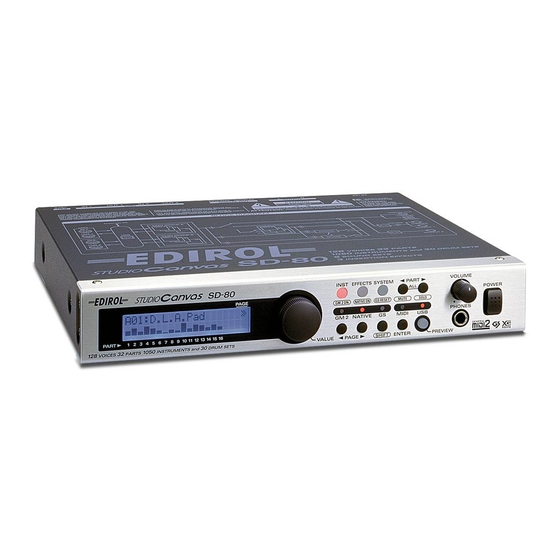
SD-80
Advertisement
Table of Contents

Related Manuals for Roland Edirol StudioCanvas SD-80


Summary of Contents for Roland Edirol StudioCanvas SD-80
-
Page 1: Table Of Contents
CIRCUIT DIAGRAM (JACK SHEET 2/2) ....39 BLOCK DIAGRAM............17 ERROR MESSAGES ............41 CIRCUIT BOARD (MAIN BOARD)......19 Copyright © 2002 ROLAND CORPORATION All rights reserved. No part of this publication may be reproduced in any form without the written permission of ROLAND CORPORATION. 17058084E0... -
Page 2: Specifications
May.2002 SPECIFICATIONS Number of parts Maximum Polyphony 128 voices Preset Sounds Sound Maps: 6 (Classical, Contemporary, Solo, Enhanced, Special1, Special2) Instruments: 1050 Drum Sound Sets: 30 User Sounds Instruments: 128 Drum Sound Sets: 16 Effects System Effects: Reverb (6 types), Chorus (6 types) Insertion Effects: Multi-effects x 3 (90 types) Display 20 characters, 2 lines (backlight LCD) - Page 3 SD-80...
-
Page 4: Location Of Controls Parts List
May.2002 SD-80 LOCATION OF CONTROLS LOCATION OF CONTROLS PARTS LIST fig.bunkai- PART PART NAME DESCRIPTION Q’TY CODE 02675701 WIRING ASSY WIRING W3(AC IN- LET+GND) 13449146 YKB21-5012 (W/ 6.5MM JACK 02565390 GP1FA501TZ OPTICAL CONNECTOR 01343723 YKC21-3117(OR- RCA(PIN) JACK ANGE) 01454945 SSSF112-S06N1 SLIDE SWITCH 02892878 2DJ-0060003... -
Page 5: Exploded View Parts List
May.2002 EXPLODED VIEW PARTS LIST [Parts] PART CODE PART NAME DESCRIPTION Q’TY 02906245 TOP COVER 02906145 BOTTOM CHASSIS 02906190 FRONT PANEL 02906189 DISPLAY COVER 02906201 S R-KNOB L DBL 02906178 RUBBER SW 02892512 P R-KNOB MF-A DBL/LCG 02781501 P S-KEY MX DBL 22225375 P B-ESCT SD1H BLK... -
Page 6: Exploded View
SD-80 EXPLODED VIEW fig.explo... -
Page 7: Parts List
May.2002 PARTS LIST fig.part1e CONSIDERATION ON PARTS ORDRING SAFETY PRECAUTIONS: When ordering any parts listed in the parts list, please specify the following items in the order sheet. The parts marked have PART NUMBER DESCRIPTION MODEL NUMBER safety-related characteristics. Use 22575241 Sharp Key C-20/50... - Page 8 SD-80 PCB ASSY 72120523 LCD BOARD ASSY NOTE: ‘LCD BOARD ASSY’ includes the following parts. 02453345 LCD HOLDER 02908834 LEAF REFLECTOR 72120512 PANEL BOARD ASSY 72120501 JACK2 BOARD ASSY NOTE: ‘JACK2 BOARD ASSY’ includes the following parts. 12199584 GROUNDING TERMINAL M1698 TER1 on J1B,TER3,TER2 on J2B 72120490...
- Page 9 May.2002 RESISTOR 00567201 RPC05T 272 J MTL.FILM RESISTOR R98,R64,R96,R68 on MB 00567245 RPC05T 472 J MTL.FILM RESISTOR R111,R108,R110,R109 on MB ,R36,R37 on 00567267 RPC05T 682 J MTL.FILM RESISTOR R65,R66,R69,R70,R75,R81,R97,R99 on MB 00567278 RPC05T 822 J MTL.FILM RESISTOR R82,R76,R71,R67 on MB 00567289 RPC05T 103 J MTL.FILM RESISTOR...
- Page 10 SD-80 CAPACITOR 02905590 4SVP330 ELECTROLYTIC CAPACITOR C6 on MB 15369263 ECEV1HA2R2SR ELECTROLYTIC CAPACITOR C98 on MB 01904856 ECEV1CA470WR ELECTROLYTIC CAPACITOR C174,C220,C219,C218,C217,C169,C192,C19 5 on MB 02124923 RV3-25V470MZ7-R ELECTROLYTIC CAPACITOR C203,C209,C206,C197,C191 on MB 02345234 RV2-6V101M-R ELECTROLYTIC CAPACITOR C4,C208,C135 on MB 01893267 TCFGA0J106M8R TANTALUM CAPACITOR C106,C32,C16,C42,C139 on MB 01675278...
- Page 11 May.2002 SCREW 40016423 JACK NUT HLJ0999-01-250 12X14X2P 1.0 17048631 VR ACCESSORY WASHER M9 17048630 VR ACCESSORY NUT M9 PACKING 02905634 PACKING CASE SLEEVE ENGLISH 02906212 PACKING CASE SLEEVE JAPANESE 03012078 PAD UPPER 02906101 PAD ADAPTOR 02906112 PAD LOWER 02906223 PACKING CASE 02906234 OUTER PACKING CASE MISCELLANEOUS...
-
Page 12: Checking The Version Number
SD-80 CHECKING THE VERSION Press the [SYSTEM] button, then press the [PAGE>] button to display Bulk Dump. NUMBER Display the USER AREA by rotating the [VALUE] control. Start sequencer recording. While holding down the [INST], [PART>] and [SHIFT] buttons, turn on the Press the [ENTER] button of the SD-80. - Page 13 May.2002 When using USB Be sure to perform factory resetting after updating. Necessary items · SD-80 and AC power cord When using the MIDI-IN terminal · Computer equipped with a USB terminal (OS: Windows98/Me/2000) · USB cable · Applications to replay the SMF (recommended: Windows MediaPlayer) Necessary items ·...
-
Page 14: Test Mode
Part of the updating file was not loaded properly. · Monitor speaker (with built-in amplifier) Action: · A device (DAT recorder, Roland UA-30 or equivalent) equipped with digital Turn off the power of the SD-80. Then turn it on again and restart updating. INPUT terminals (optical or coaxial) - Page 15 May.2002 MIDI check fig.3-5a_65 Check if MIDI communication is done properly. 1. Set the switch on the back of the SD-80 to “OUT 2”. 2. Connect MIDI IN 1 to MIDI OUT 1 of the SD-80 and MIDI IN 2 to MIDI OUT 2 with the MIDI cable, respectively.
- Page 16 SD-80 sound by listening to it through the headphones. Press the same button to stop the effect. fig.3-8_65 Press the [INST] button to send a snare sound at an interval of 2.5 seconds from the power source. Make sure that a delayed sound is heard after the original snare sound.
-
Page 17: Block Diagram
May.2002 SD-80 BLOCK DIAGRAM fig.block ig.cable S W2 J K7 JK 3 J K4 J K5 J K6 J K2 CN 2 V R1 W IR IN G 4X200-P 2. 0-PH R-PH R-F 02342012 J AC K1 B OA RD V OL UME B OA RD J AC K2 B OA RD AS S Y 72120490... -
Page 18: Circuit Board (Main Board)
May.2002 CIRCUIT BOARD (MAIN BOARD) fig.mb-sch1... -
Page 19: Circuit Board (Jack Sheet)
SD-80 CIRCUIT BOARD (JACK SHEET) fig.mb-sch1... -
Page 20: Circuit Diagram (Main Board 1/7)
May.2002 SD-80 CIRCUIT DIAGRAM (MAIN BOARD 1/7) fig.mb-sch1 MAIN BOARD BLOCK DIAGRAM LEVEL CONVER T C PU Block USB Block B l o c k 12MHZ 12MHZ 3D[0..15] D[0..15] 3D[0..15] 3D[0..15] D[0..15] D[0..15] P OWER B LOCK 3A[1..8] A[1..8] 3A[1..8] 3A[1..8] A[1..8] A[1..8]... -
Page 21: Circuit Diagram (Main Board 2/7)
May.2002 SD-80 CIRCUIT DIAGRAM (MAIN BOARD 2/7) fig.mb-sch2 C PU Block 3A24 LEVEL _C ONV. 3A[1..8] B l o c k 3D[0..15] 3RDWR R D/WR 3XWRUU WE3/DQMUU/ICIOWR/PT C[2] 3XWRUL R A 1 3A24 WE2/DQMUL/ICIOR D/PT C[1] 3XWRLU 3XWRLU WE1/DQMLU/WE 3XWRLL R A 2 3A21 WE0/DQMLL... -
Page 22: Circuit Diagram (Main Board 3/7)
May.2002 SD-80 CIRCUIT DIAGRAM (MAIN BOARD 3/7) fig.mb-sch3 LEV EL CONV ER TE RB l o ck INT ER F ACE BLOC K D 3. 3 X RS TC PU IC7B DTB 113ZK B l o ck IC7A LV00A P OWER LV00A C 57 C 76... -
Page 23: Circuit Diagram (Main Board 4/7)
May.2002 SD-80 CIRCUIT DIAGRAM (MAIN BOARD 4/7) fig.mb-sch4 USB Block C 89 OS-CON 10u/16V C 91 C 90 0.1u 0.1u C 92 0.1u USB DP C NV SS C 93 0.1u R 31 USB DN 1.5k R 27 C 94 INT ER F ACE 680P S W2A... -
Page 24: Circuit Diagram (Main Board 5/7)
May.2002 SD-80 CIRCUIT DIAGRAM (MAIN BOARD 5/7) fig.mb-sch5 100u/6.3V XWB AC K XWB RE Q TONE G ENER ATOR #0 BLOC K C104 XWC S0 0.1u WA[0..23] D 3. 3 C106 C105 WD[0..15] 10u/6.3V 0.1u XWOE C107 0.1u C108 0.1u C109 3WA[0..22] 0.1u... -
Page 25: Circuit Diagram (Main Board 6/7)
May.2002 SD-80 CIRCUIT DIAGRAM (MAIN BOARD 6/7) fig.mb-sch6 C135 100u/6.3V TONE G ENER ATOR #1 BLOC K C136 0.1u C137 C139 D 3. 3 0.1u 10u/6.3V C138 0.1u C140 0.1u C141 0.1u C142 C143 0.1u 0.1u C144 C145 0.1u 0.1u C146 C147 0.1u... -
Page 26: Circuit Diagram (Main Board 7/7)
May.2002 SD-80 CIRCUIT DIAGRAM (MAIN BOARD 7/7) fig.mb-sch7... -
Page 27: Circuit Board (Jack Sheet)
May.2002 CIRCUIT BOARD (JACK SHEET) fig.mb-sch7... - Page 28 SD-80 fig.mb-sch7...
-
Page 29: Circuit Diagram (Jack Sheet 1/2)
May.2002 SD-80 CIRCUIT DIAGRAM (JACK SHEET 1/2) fig.jk-sch1CIRCUIT BOARD (MAIN) DOU T JACK1 BOAR D 0.1u J K8 AS S Y72120490 R 38 IC1A IC1B C 17 R 13 R 14 YK B21-5012 HCU04 HCU04 47u/25V OUTPUT1R C N2 G P1FA501TZ R 15 C 18 C 40... -
Page 30: Circuit Diagram (Jack Sheet 2/2)
May.2002 SD-80 CIRCUIT DIAGRAM (JACK SHEET 2/2) fig.jk-sch2 to J AC K1 V OLUME B OARD E NC ODER BOAR D B oard AS S Y72120534 AS S Y72120545 C N10 OUT 1R S 4B -P H-K-S from OUT 1L E N1A MAIN E C12E2420801... -
Page 31: Error Messages
May.2002 ERROR MESSAGES When data are not processed properly or when other problems occur, an error message appears. When an error message appears, take the following actions. MIDI Error Cause 1: Power of the MIDI device connected to the MIDI IN connector may have failed.
Need help?
Do you have a question about the Edirol StudioCanvas SD-80 and is the answer not in the manual?
Questions and answers