Table of Contents
Advertisement
Quick Links
Advertisement
Table of Contents

Related Manuals for Asus GQE10A


Summary of Contents for Asus GQE10A
- Page 1 ASUS-Google Meet hardware kit GQE10A User Guide...
- Page 3 Copyright © 2020 ASUSTeK COMPUTER INC. All Rights Reserved. LIMITATION OF LIABILITY Circumstances may arise where because of a default on ASUS’ part or other liability, you are entitled to recover damages from ASUS. In each such instance, regardless of the basis on which you are entitled to claim damages from ASUS, ASUS is liable for no more than damages for bodily injury (including death) and damage to real property and tangible personal property;...
-
Page 4: Table Of Contents
Contents About this user guide ......................6 Package contents ........................7 Getting to know your Meeting Computer System Features .............................12 Rear view ..........................12 Left side view ..........................14 Right side view ........................14 Bottom view ..........................15 Using your Meet hardware kit Getting started ........................18 Connect a display panel to your Meeting Computer System .......18 Connect the speakermic.....................19 Connect the camera ......................20... - Page 5 Appendix Safety information .........................50 Setting up your system .......................50 Care during use ........................50 Regulatory notices ........................52 ASUS contact information ....................65...
-
Page 6: About This User Guide
About this user guide This user guide provides information about the hardware and software features of your Meet hardware kit, organized through the following chapters: Chapter 1: Getting to know your Meeting Computer System This chapter details the hardware components of your Meeting Computer System. -
Page 7: Package Contents
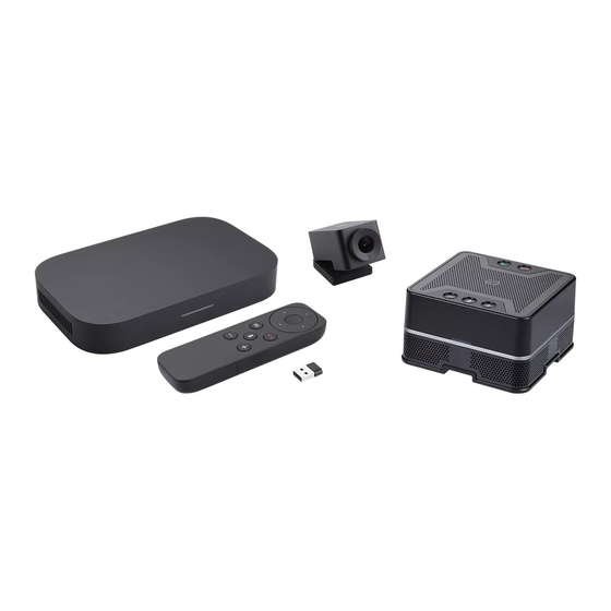
Package contents Your Meet hardware kit package contains the items detailed below. You can also refer to the Meet hardware kit peripheral table for details on the peripheral items included in the different kits. Meeting Computer System items: Meeting Computer System Wall mounting plate Power cable* Wall mounting plate screw set... - Page 8 Peripheral items: Touchscreen power adapter Touchscreen Touchscreen adapter plug heads* Touchscreen HDMI™ cable Touchscreen USB power Touchscreen USB data cable (Green) cable (Red) (Blue)** Camera Speakermic Remote Control USB dongle Camera USB cable Speakermic cable Batteries (Type-A to USB Type-C®) (Type-A to Micro USB) * The bundled power adapter plug heads may vary with territories...
- Page 9 If the device or its components fail or malfunction during normal and proper use within the warranty period, bring the warranty card to the ASUS Service Center for replacement of the defective components. • Some bundled accessories may vary with different models.
-
Page 11: Getting To Know Your Meeting Computer System
Getting to know your Meeting Computer System... -
Page 12: Features
Features Rear view Power button The power button allows you to turn the Meeting Computer System on or off. You can use the power button to put your Meeting Computer System to sleep mode or press it for four (4) seconds to force shutdown your Meeting Computer System. - Page 13 USB 3.2 Gen 1 port The USB 3.2 Gen 1 (Universal Serial Bus) port provides a transfer rate up to 5 Gbit/s. This port also supports the Battery Charging 1.2 technology that allows you to charge your USB devices. NOTE: Battery Charging 1.2 technology is only available on selected models, and provides a maximum of 5V / 1.5A output.
-
Page 14: Left Side View
Left side view Air vents (intake vent) The air vents allow cooler air to enter your Meeting Computer System chassis. IMPORTANT! For an optimum heat dissipation and air ventilation, ensure that the air vents are free from obstructions. Right side view Air vents (exhaust vent) The air vents allow your Meeting Computer System chassis to expel hot air out. -
Page 15: Bottom View
Bottom view Mount pad slot The mount slot is used to attach the Meeting Computer System to the standing mount. -
Page 17: Using Your Meet Hardware Kit
Using your Meet hardware... -
Page 18: Getting Started
Getting started Connect a display panel to your Meeting Computer System You can connect a display panel or projector that has the following connectors: • HDMI™ connector • DisplayPort (USB Type-C ® • DVI connector (used with an HDMI™–DVI adapter) NOTE: •... -
Page 19: Connect The Speakermic
Connect the speakermic Connect the speakermic to a USB 3.2 Gen 1 port on the rear of your Meeting Computer System. NOTE: Please refer to pages 37-38 for more information on the recommended USB 3.2 Gen 1 port to connect the speakermic to. -
Page 20: Connect The Camera
Connect the camera Connect the camera to a USB 3.2 Gen 1 port on the rear of your Meeting Computer System. NOTE: Please refer to pages 37-38 for more information on the recommended USB 3.2 Gen 1 port to connect the camera to. -
Page 21: Connect The Touchscreen
Connect the touchscreen To connect the touchscreen to your Meeting Computer System NOTE: Ensure to use the Touchscreen USB data cable (Blue). Connect the Touchscreen USB data cable (Blue) to the data USB port on your touchscreen. Connect the touchscreen to a USB 3.2 Gen 1 port on the rear of your Meeting Computer System. - Page 22 To connect the AC power adapter of your touchscreen NOTE: Ensure to use the Touchscreen USB power cable (Red). Connect the Touchscreen USB power cable (Red) to the AC power adapter. Connect the Touchscreen USB power cable (Red) to the power USB port on your touchscreen.
- Page 23 To connect the touchscreen for local presentations (optional) NOTE: Ensure to use the Touchscreen HDMI™ cable (Green). Connect the Touchscreen HDMI™ cable (Green) to the HDMI™ port on your touchscreen. Connect the touchscreen to a device’s (such as a laptop) HDMI™ out port for local presentations.
-
Page 24: Connect The Remote Control Dongle To Your Meeting Computer System
Connect the remote control dongle to your Meeting Computer System Connect the remote control USB dongle to a USB 3.2 Gen 1 port on the rear of your Meeting Computer System. -
Page 25: Connect The Ac Power Adapter To Your Meeting Computer System
Connect the AC power adapter to your Meeting Computer System To connect the AC power adapter to your Meeting Computer System: Connect the AC power cord to the AC/DC adapter. Connect the DC power connector into your Meeting Computer System’s power (DC) input port. Plug the AC power cord into a 100V~240V power source. - Page 26 IMPORTANT! • We strongly recommend that you use only the AC power adapter that came with your Meeting Computer System. • We strongly recommend that you use a grounded wall socket while using your Meeting Computer System. • The socket outlet must be easily accessible and near your Meeting Computer System.
-
Page 27: Turn On Your Meeting Computer System
Turn on your Meeting Computer System Press the power button to turn on your Meeting Computer System. IMPORTANT! Ensure that all peripherals (speakermic, camera, touchscreen) and AC power adapter are connected properly before you turn on your Meeting Computer System. -
Page 29: Configuring Your Meet Hardware Kit
Configuring your Meet hardware kit... -
Page 30: Before You Begin Using Your Device For Video Conferencing
Before you begin using your device for video conferencing Setup requirements Room size and setup Your Meet hardware kit system is designed for a conference room of up to 20 persons. We recommend a room that contains either a long table with the monitor at one end (optimal), or a round table. - Page 31 Display requirements and placement Your Meeting Computer System work with LCD, LED, plasma, and projector- type monitors and televisions. The display must have an HDMI™ or DisplayPort input. You can place the display on a table against one wall, or mount the display on a wall or ceiling for a projector unit.
-
Page 32: Setup Your System
• Cable concealers, if needed for wall mounting NOTE: The cable concealers for wall mounting and CAT5e Ethernet cable are not included in the package and must be purchased separately. IMPORTANT! The included cable for the camera is 5 feet long, and the included cable for the speakermic is 3 feet long. - Page 33 Secure the wall mount to a wall using the four (4) screws. NOTE: The screws are self tapping M3.5 24 mm long, flat countersunk head type screws. Locate the mount pad slot on the bottom of your device and orientate it as shown in the illustration below so that the exhaust air vents faces upwards.
- Page 34 Your device will be magnetized onto the wall mount plate, please ensure the mount pad slots are aligned with the wall mount before placing the device onto the wall mount plate. NOTE: Please refer to Chapter 1 Getting to know your Meeting Computer System for more information on the location of the mount pad slots.
- Page 35 Using the standing mount To attach your Meeting Computer System to the bundled standing mount, please follow the steps below: Locate the mount pad slot on the bottom of your device and orientate it as shown in the illustration below so that the exhaust air vents faces upwards.
- Page 36 Align your device’s mount pad slot to the standing mount, then bring the device closer to the mount. Your device will be magnetized and attach onto the standing mount. Manually adjust your device if needed for a more secure fit.
- Page 37 You may install your camera below or on top of the display depending on the screen height. NOTE: Keep the camera as close to eye level as possible. Recommended meeting room configuration 1 System setup GQE10A WALL MOUNT MEET CAMERA DISPLAY CHROMEBOX (WITH VESA MOUNT MOUNTED TO DISPLAY) MICROPHONE &...
- Page 38 Room layout example DISPLAY note 1 MEET AUTOZOOM RANGE 3.5M (11'-6") CAMERA NOTES: Nearest viewing position, recommend 1.5 x screen height. Camera field of view.
- Page 39 Recommended meeting room configuration 2 System setup GQE10A MEET CAMERA MEET CAMERA DISPLAY DISPLAY MICROPHONE & SPEAKER TOUCH PANEL CREDENZA RECOMMENDED HEIGHT BETWEEN CREDENZA 750 - 1000mm " - 39 "] CHROMEBOX OPTIONAL USB HUB FRONT WALL EXAMPLE EQUIPMENT LAYOUT...
- Page 40 Room layout example DISPLAY MEET CAMERA...
- Page 41 Connect your cables Using the included cables and sensor, connect your Meeting Computer System to the other system components: NOTE: The connections shown in the illustrations are recommended, you may adjust the connections accordingly to suit your needs. LAN port connects to a router. NOTE: Although you can use your Meeting Computer System device over a wireless network connection, we recommend using a wired network connection for optimal sound and video quality.
- Page 42 USB 3.2 Gen 1 port connects the camera. USB 3.2 Gen 1 port connects to the touchscreen HDMI™ connects a display with HDMI™ connector. DisplayPort connects a display with USB Type-C connector. ® Power port connects to a power outlet. IMPORTANT! Be sure to connect to a power outlet last, after you have made all the other connections.
-
Page 43: Enroll Your Device
Enroll your device Complete basic enrollment This section explains the basic enrollment flow, which works for almost all users. To learn about other options shown during the enrollment process, see Advanced enrollment options. NOTE: We recommend connecting a USB keyboard to make entering the enrollment information easier. - Page 44 Select Continue. Accept the Google Chrome OS Terms. Sign in with your Google Apps email address and password. The enrollment process takes place automatically. After the process is complete, click Done. When the Hangouts screen appears, follow the onscreen instructions to test your camera and speakermic.
- Page 45 Advanced enrollment options Users can go through the simple enrollment flow described in Complete basic enrollment to enroll their device. Additional options are available for users who want to customize the setup experience or learn more. These options appear on the second enrollment screen, except for accessibility, which appears on both the first and second screens: Accessibility: Accessibility options include larger font and cursor size, voice prompts, and more.
-
Page 46: Manage Devices And Rooms
Manage devices and rooms You can view, modify and update your Meeting Computer System and rooms through the Google Admin console. For more details on managing your devices and rooms, please visit the Meeting Computer System Help website. -
Page 47: Troubleshooting
Troubleshooting... -
Page 48: Fix A Problem
Fix a problem Manage devices and rooms I do not know how to identify the Meeting Computer System device I want on the device list screen. If you are not sure which device to click, you can identify the correct one by its serial number. -
Page 49: Appendix
Appendix... -
Page 50: Safety Information
Safety information Your Meeting Computer System is designed and tested to meet the latest standards of safety for information technology equipment. However, to ensure your safety, it is important that you read the following safety instructions. Setting up your system •... - Page 51 – Liquid has been spilled into the system. – The system does not function properly even if you follow the operating instructions. – The system was dropped or the cabinet is damaged. – The system performance changes. • Avoid contact with hot components inside the Mini PC. During operation, some components become hot enough to burn the skin.
-
Page 52: Regulatory Notices
Regulatory notices COATING NOTICE IMPORTANT! To provide electrical insulation and maintain electrical safety, a coating is applied to insulate the device except on the areas where the I/O ports are located. Federal Communications Commission Statement This device complies with Part 15 of the FCC Rules. Operation is subject to the following two conditions: (1) This device may not cause harmful interference, and (2) This device must accept any interference received, including interference... - Page 53 For the frequency 5600-5650 MHz, no operation is permitted Pour la fréquence 5600-5650 MHz, aucune opération est autorisée. Responsible Party: Asus Computer International Address: 48720 Kato Rd, Fremont, CA 94538 Phone/Fax No:...
- Page 54 Wireless Operation Channel for Different Domains N. America 2.412-2.462 GHz Ch01 through CH11 Japan 2.412-2.484 GHz Ch01 through Ch14 Europe ETSI 2.412-2.472 GHz Ch01 through Ch13 Regional notice for Singapore Complies with This ASUS product complies with IMDA Standards. IMDA Standards DA105282...
- Page 55 ASUS follows the green design concept to design and manufacture our products, and makes sure that each stage of the product life cycle of ASUS product is in line with global environmental regulations. In addition, ASUS disclose the relevant information based on regulation requirements.
- Page 56 ASUS products sold in Vietnam, on or after September 23, 2011,meet the requirements of the Vietnam Circular 30/2011/TT-BCT. Các sản phẩm ASUS bán tại Việt Nam, vào ngày 23 tháng 9 năm2011 trở về sau, đều phải đáp ứng các yêu cầu của Thông tư 30/2011/TT-BCT của Việt Nam.
- Page 57 NOTE: Energy Star is NOT supported on FreeDOS and Linux-based products. EPEAT (Electronic Product Environmental Assessment Tool) registered products The public disclosure of key environmental information for ASUS EPEAT registered products is available on CSR web site http://csr.asus.com/english/ article.aspx?id=41. More information about EPEAT program and purchaser...
- Page 58 ASUSTek Computer Inc. con la presente dichiara che questo dispositivo è conforme ai requisiti essenziali e alle altre disposizioni pertinenti con la direttiva 2014/53/EU. Il testo completo della dichiarazione di conformità UE è disponibile all’indirizzo: https://www.asus.com/Commercial-Desktop/ASUS-Hangouts- Meet-hardware-kit/HelpDesk_Declaration/ L’utilizzo della rete Wi-Fi con frequenza compresa nell’intervallo 5150-5350MHz deve essere limitato...
- Page 59 С настоящото ASUSTek Computer Inc. декларира, че това устройство е в съответствие със съществените изисквания и другите приложими постановления на свързаната Директива 2014/53/ EC. Пълният текст на ЕС декларация за съвместимост е достъпен на адрес https://www.asus.com/ Commercial-Desktop/ASUS-Hangouts-Meet-hardware-kit/HelpDesk_Declaration/ WiFi, работеща в диапазон 5150-5350MHz, трябва да се ограничи до употреба на закрито за страните, посочени...
- Page 60 De WiFi op 5150-5350MHz zal beperkt zijn tot binnengebruik voor in de tabel vermelde landen: Lihtsustatud EÜ vastavusdeklaratsioon Käesolevaga kinnitab ASUSTek Computer Inc, et seade vastab direktiivi 2014/53/EÜ olulistele nõuetele ja teistele asjakohastele sätetele. EL vastavusdeklaratsiooni täistekst on saadaval veebisaidil https://www.asus. com/Commercial-Desktop/ASUS-Hangouts-Meet-hardware-kit/HelpDesk_Declaration/ Sagedusvahemikus 5150-5350 MHz töötava WiFi kasutamine on järgmistes riikides lubatud ainult...
- Page 61 Firma ASUSTek Computer Inc. niniejszym oświadcza, że urządzenie to jest zgodne z zasadniczymi wymogami i innymi właściwymi postanowieniami dyrektywy 2014/53/EU. Pełny tekst deklaracji zgodności UE jest dostępny pod adresem https://www.asus.com/Commercial-Desktop/ASUS-Hangouts-Meet- hardware-kit/HelpDesk_Declaration/ W krajach wymienionych w tabeli działanie sieci Wi-Fi w paśmie 5150–5350 MHz powinno być ograniczone wyłącznie do pomieszczeń:...
- Page 62 Spoločnosť ASUSTek Computer Inc. týmto vyhlasuje, že toto zariadenie je v súlade so základnými požiadavkami a ďalšími príslušnými ustanoveniami smernice č. 2014/53/EÚ. Plné znenie vyhlásenia o zhode pre EÚ je k dispozícii na lokalite https://www.asus.com/Commercial-Desktop/ ASUS-Hangouts-Meet-hardware-kit/HelpDesk_Declaration/ Činnosť WiFi v pásme 5150 - 5350 MHz bude obmedzená na použitie vo vnútornom prostredí pre krajiny uvedené...
- Page 63 This is a Class A product, in a domestic environment, this product may cause radio interference, in which case the user may be required to take adequate measures. 7265NGW (Model: GQE10A) output power table: Function Frequency Maximum Output Power (EIRP)
- Page 64 Manufacturer ASUSTeK Computer Inc. Tel: +886-2-2894-3447 Address: 1F., No. 15, Lide Rd., Beitou Dist., Taipei City 112, Taiwan Authorised ASUSTeK Computer GmbH representative in Address: Harkortstrasse 21-23, 40880 Europe Ratingen, Germany...
-
Page 65: Asus Contact Information
+1-510-739-3777 +1-510-608-4555 Web site https://www.asus.com/us/ Technical Support Support fax +1-812-284-0883 Telephone +1-812-282-2787 Online support https://qr.asus.com/techserv ASUS COMPUTER GmbH (Germany and Austria) Address Harkortstrasse 21-23, 40880 Ratingen, Germany Web site https://www.asus.com/de Online contact https://www.asus.com/support/Product/ ContactUs/Services/questionform/?lang=de-de Technical Support Telephone (DE) +49-2102-5789557 Telephone (AT) - Page 66 FCC COMPLIANCE INFORMATION Per FCC Part 2 Section 2.1077 Asus Computer International Responsible Party: 48720 Kato Rd, Fremont CA 94538. Address: Phone/Fax No: (510)739-3777/(510)608-4555 hereby declares that the product Product Name : Meeting Computer System Model Number : GQE10A compliance statement: This device complies with part 15 of the FCC Rules.
Need help?
Do you have a question about the GQE10A and is the answer not in the manual?
Questions and answers