Table of Contents
Advertisement
Quick Links
Thank you for using our CONOTEC's products.
Please, be sure to read "Handling Precautions" before use, and use this product correctly.
After reading this user manual, keep it in a place where you can see at any time.
It will be much more convenient when you use this product after reading this user manual.
Manual Version: V1.0
Advertisement
Table of Contents

Related Manuals for Conotec i300


Summary of Contents for Conotec i300
- Page 1 Thank you for using our CONOTEC’s products. Please, be sure to read "Handling Precautions" before use, and use this product correctly. After reading this user manual, keep it in a place where you can see at any time. It will be much more convenient when you use this product after reading this user manual.
- Page 2 ※ CONOTEC’s services are also the best. Through our dealer where you purchased this product, you can report on the failure or discomfort in use. To improve the performance of the products, the specifications of this product are subject to change without prior notice.
-
Page 3: Table Of Contents
Contents Handling Precautions Components Product appearance and panel processing dimension Terminal wiring methods and input/out specifications Special Feature Switch and Display Menu Road Map Basic Menu Detailed Temperature Setting Communication Control Output Others Quality Warranty... -
Page 4: Handling Precautions
Handling Precautions Thank you for purchasing our CONOTEC’s products. In order to use this product, please be aware of the details below. Safety Precautions Warnings 1. This product has not been manufactured as a safety device; therefore, in the case that this product is going to be used for controls, such as devices from... - Page 5 15. Do not use near devices causing strong high-frequency noise (high-frequency welders, high-frequency sewing machines, high-frequency radios, large SCR controller). 16. When using methods other than specified by the manufacturer, injury or property damage may occur. 17. Please keep out of children’s reach, since it is not a toy. 18.
-
Page 6: Components
Components Product Bracket Sensor... -
Page 7: Product Appearance And Panel Processing Dimension
Product appearance and panel dimension Unit Error Product dimension Panel processing dimension... -
Page 8: Terminal Wiring Methods And Input/Out Specifications
Terminal wiring methods and input/out specifications Input Voltage Output Voltage: The same as input voltage Output contact capacity: Relay contact output (5A 250VAC) Input Port: 3 Ports no power contact Output Port: 7 Ports Sensor Temperature Range Input Port Output Comm. -
Page 9: Special Feature
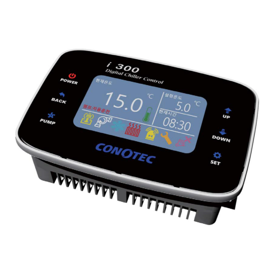
Special Feature and Touch Function With TET-LCD and touch, much information and colors can be displayed and easy operation and recognition support a user-oriented interface. ※ The product uses a capacitive touch method and thus requires precautions as the key may cause malfunction if touched with wet hands or used with thick gloves. -
Page 10: Switch And Display
Switch and Display Power: A button to start or stop a system. Cancel: A button to move to the previous menu at the time of setting or to return to the basic screen Pump: A button for automatic operation of the pump operation mode / and to switch to the manual operation Top: A button to move to the menu in the setting or a button that increases the setpoint upon changing... - Page 11 Menu Load Map System press for 5 seconds press for 5 seconds For more details on blackout restoration / delay time, refer to pages 14-15. Output status / The current time (the telephone number to the installer) / View alarm history press for 5 seconds...
- Page 12 Pump Operation Mode Change press for 5 seconds The system should be stopped to change the mode of pump operation. Mute Mode press for 5 seconds When the alarm buzzer goes off, the buzzer sound can be turned off by activating the mute mode.
- Page 13 Basic temperature settings Detailed Menu Settings press for 5 seconds See Page 15 See Page 15 See Page 16...
- Page 14 See Page 19 See Page 18 See Page 19 See Page 19 See Page 19 See Page 19...
-
Page 15: Basic Menu
Basic Menu Basic Temperature Settings Factor Setting Setting range Unit Reset Temperature Deviation Setting Temperature Setup the basic temperature for operation Temperature Deviation A regular interval is required between ON and OFF in the ON/OFF control (set up ON/OFF width) Frequent ON and OFF will shorten the lifespan of the relay or the output contact or cause hunting (generation, chattering) by noise from outside. -
Page 16: Detailed Temperature Setting
Detailed Temperature Setting Detailed Temperature Setting Setting Item Factory Reset Setting Range Unit Setting Temperature Temperature Deviation Sensor Calibration Temperature Setting The same as the default temperature settings (See page 14) Temperature Deviation The same as the default temperature settings (See page 14) Sensor Calibration While there is no problem in the product, if the temperature shown in the display window and the actual temperature are differed, the function calibrates... - Page 17 Pump Delay Time The same as the Comp. delay time (See page 13) Pump Down Time The function to setup the delay time until Comp. output comes to stop after the solenoid valve is OFF upon the termination of cooling/heating/thermostatic operation.
- Page 18 System System E.g.) Suppose stop delay time is 60 seconds, the system is turned OFF at and the output of the SV/COMP in operation will be turned OFF. And the system will be delayed until the time (60 seconds) of and the pump relay will be turned OFF.
- Page 19 Exterior Input Setting Setting Item Factor Reset Setting Range Unit Pump Input Time Pump Input Type 5 Sec. Comp. Input Time Comp. Input Type 5 Sec. Water Circulation Time Water Circulation Type 5 Sec. Pump Input Time The function detects signal of pump input during the setting time or sets up detection time to set the alarm when not detected.
- Page 20 Equipment Output Test Setting Item Setting Range Valve Pump Comp. Stop/On Heater Alarm Comp. Preparation Pump Preparation Equipment Output Test To test connected operation devices after installation, change the setpoint. The setpoint will be reset to stop if exit the menu without saving the setpoint. Current Time Setting Setting Item Setting Range Unit...
-
Page 21: Communication Control Output
Communication Control Output Interface Applicable Standard EIA RS485 Reference The Max. Number of Connection 32 units (Communication codes can be set between 1 to 99) Communication Method Two-wire, Half Duplex Communication System Asynchronous Communication Distance Within 1 .2Km Communication Speed 1200/2400/4800/9600/19200bps (Optional) Start Bit 1Bit Fixed... - Page 22 Composition 1. The communication protocol of i300 is Modus RTU. 2. The master sends query and the slave sends responses. Definition of Communication Command Block Host Query Format Code Number Command Starting address Number of Data The range of CRC16 Check Sum calculation ①...
- Page 23 Response Format of the Product Address Command Number of Data Data (Top) Data (Bottom) The range of CRC16 Check Sum calculation ① Area Code: The host system is the area code that identifies products. They can be set within the range of 1-99. ②...
- Page 24 Classification Setting Range Unit Remarks 0: On, 1: Stop Classification Setting Range Unit Remarks Valve Comp. Pump Heater Alarm Sub Comp. Sub Pump Repair Comp. Input Pump Input Water Circulation Input Pump Mode Manual, Automatic Mute Main Screen Classification Setting Range Unit Remarks Current Temperature...
- Page 25 Main Screen Classification Setting Range Remarks Unit Current Time (Year) Current Time (Month) Current Time (Date) Current Time (Day) 0: Sun, 1: Mon, 2: Tue, 3: Wed, 4: Thur, 5: Fri, 6: Sat Current Time (Time) Current Time (Minute) Min. Current Time (Second) Sec.
- Page 26 Temperature Setting Classification Setting Range Unit Remarks Temperature Setting Temperature Deviation Temperature Calibration Delay Time Setting Unit Setting Range Classification Remarks Comp. Delay Time Sec. Pump Delay Time Sec. Pump Down Time Sec. Power Operation Setting Classification Setting Range Unit Blackout Return Time Sec.
- Page 27 Equipment Output Test Remarks Classification Setting Range Unit Valve Output Pump Output Comp. Output 0: Stop / 1: On Heater Output Alarm Output Sub Comp. Output Sub Pump Output Current Time Setting Setting Range Unit Remarks Classification Year Year Month Month Date Date...
- Page 28 Others Sensor Error Display If the sensor cable is cut in the middle or has loose connection in the terminal block: If short circuit occurred between sensor wire: Memory Error Display In the event of frequent error display, please contact to customer service department.
- Page 32 Feb 25, 2016...
Need help?
Do you have a question about the i300 and is the answer not in the manual?
Questions and answers