Table of Contents
Advertisement
INSTALLATION & START-UP GUIDE
WARNING!
NO OIL
is shipped in compressor.
Compressor must
Oxygen is never to be used to pressure test any refrigerant system.
These Safeties ARE Required at Startup to Maintain Hanbell Warranty
a) Motor Module Trip (INT69HBY): Open for 1 second
b)
Low Oil Level Float Trip: Open for 30-60 seconds
c)
Unsafe Suction: Less than 5 psi for 3 seconds
d)
Low Differential Pressure: Less than 65 psi for 60 seconds (Oil Psi – Suction Psi)
e)
Unsafe Differential Pressure: Less than 35 psi for 5 seconds (Oil Psi – Suction Psi)
f)
Low Discharge Superheat: Less than 25°F for 300 seconds
5580 Enterprise Pkwy., Fort Myers, FL 33905 Office (239) 694-0089 Fax: (239) 694-0031
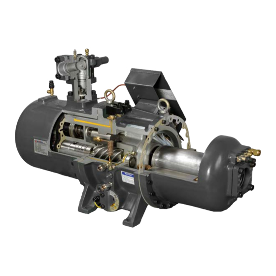
HANBELL COMPRESSOR
RC2-100 TO RC2-930
NEVER
be run backwards.
www.mcscontrols.com
Rev M.5.4
Advertisement
Table of Contents

Related Manuals for Hanbell RC2 Series


Summary of Contents for Hanbell RC2 Series
- Page 1 Oxygen is never to be used to pressure test any refrigerant system. These Safeties ARE Required at Startup to Maintain Hanbell Warranty a) Motor Module Trip (INT69HBY): Open for 1 second Low Oil Level Float Trip: Open for 30-60 seconds Unsafe Suction: Less than 5 psi for 3 seconds Low Differential Pressure: Less than 65 psi for 60 seconds (Oil Psi –...
- Page 2 COMPRESSOR INSTALLATION & START-UP GUIDE REVISION M The MCS Commitment is to provide practical solutions for the industries needs and to be both a leader and partner in the effective use of microprocessor controls. Micro Control Systems, Inc. 5580 Enterprise Parkway Fort Myers, Florida 33905 PH:(239) 694-0089 FAX:(239) 694-0031 www.mcscontrols.com...
-
Page 3: Table Of Contents
Pre-Start-Up Procedure ....................13.1. Oil Types ..............................22 6.3. HANBELL FLOODED TYPE WITH OIL SEPARATOR ................23 6.4. HANBELL FLOODED TYPE WITH OIL SEPARATOR & OIL COOLER ............24 Chapter - 14. Start-up Procedure ......................14.1. Recommended Safety Settings .........................25 Chapter - 15. -
Page 4: Chapter - 1. Compressor Crate Unpacking & Inspection
COMPRESSOR INSTALLATION & START-UP GUIDE REVISION M Chapter - 1. Compressor Crate Unpacking & Inspection 1. Inspect crate and compressor for any shipping damage. 2. The compressor is in an easy open crate, cut straps and lift off crate top from base. -
Page 5: Chapter - 2. Safety And Installation Procedures
The compressor has no oil and is not charged with oil. When adding or doing a complete change, use only the listed Hanbell approved oils. POE oils readily absorb moisture and cause acid formation in the system. Keep oil exposure to the atmosphere to a minimum. -
Page 6: Chapter - 3. Recommended Liquid Injection Piping
COMPRESSOR INSTALLATION & START-UP GUIDE REVISION M Chapter - 3. Recommended Liquid Injection Piping 1. Liquid Injection Solenoid Valve and Expansion Valve (Required, Not included with compressor): The liquid injection system may be piped, but it is necessary to consider the required space for adjustment of the expansion valve while testing or running the compressor. - Page 7 COMPRESSOR INSTALLATION & START-UP GUIDE REVISION M Chapter - 4. Electrical Wiring 1. If the compressor application is low voltage, the following items should be considered: 2. Use conduit to insulate and protect the main power cables between the control panel and compressors’ electrical terminal box.
- Page 8 COMPRESSOR INSTALLATION & START-UP GUIDE REVISION M Chapter - 5. Wiring Procedures - Y-Delta / Part Winding...
- Page 9 COMPRESSOR INSTALLATION & START-UP GUIDE REVISION M Motor Terminals The method to tell the terminals for wiring (V-Phase) 1. Star-Delta Motor - refer to Letter by terminal bolt. 2. PWS Motor - refer to Number by terminal bolt. Old Style Motor Terminals Number to right of Bolt Smaller Compressors...
- Page 10 COMPRESSOR INSTALLATION & START-UP GUIDE REVISION M Figure 5-A Motor Wiring...
-
Page 11: Electrical Power Terminals
5.1. Electrical Power Terminals The power terminals of Hanbell compressors are made from ceramic materials and are insulated more than 1000MΩ. Be careful connecting the wiring and follow the list below. ► The ceramic part on the power terminal should not be tighten by hitting otherwise the insulation of the power terminal could be degraded. -
Page 12: Chapter - 5. Across The Line Jumper Bar Installation
COMPRESSOR INSTALLATION & START-UP GUIDE REVISION M Chapter - 6. Across the Line Jumper Bar Installation Photo shows extra nuts installed under jumper bar for clearance of power bolt Insulation Connect line voltage directly on Terminal post... -
Page 13: Chapter - 6. Int69Hby Motor Protection
The module has built in flash codes that are helpful for diagnosing safety faults. In order to protect the compressor, each RC2 series compressor has been built with three PTC temperature sensors inside the motor coil and one at the discharge port neck of the compressor. These sensors are connected to the motor module to monitor coil temperature and discharge temperature. -
Page 14: Flash Code Overview
COMPRESSOR INSTALLATION & START-UP GUIDE REVISION M 7.5. Flash Code Overview Green lit Compressor Operational Green flashing Compressor Running Red/Orange flashing Error, Compressor is switched off; for description see table below flashing sequence flashing sequence Description (Red LED) (Orange LED) Motor temperature;... -
Page 15: How To Wire Int69Hby Diagnose
COMPRESSOR INSTALLATION & START-UP GUIDE REVISION M 7.6. How to Wire INT69HBY Diagnose The following diagram shows the proper wiring connections for the module. The module is connected to L1, L2 and L3 for phase monitoring. Stake on connectors at terminal “A” are connected in series with the discharge PTC and wired back to S1 and S2. -
Page 16: Chapter - 7. Rc2-100, 140 Installation Guide
COMPRESSOR INSTALLATION & START-UP GUIDE REVISION M Chapter - 8. RC2-100, 140 Installation Guide... -
Page 17: Chapter - 8. Rc2-170 ~ 580 Installation Guide
COMPRESSOR INSTALLATION & START-UP GUIDE REVISION M Chapter - 9. RC2-170 ~ 580 Installation Guide... -
Page 18: Chapter - 9. Rc2-710 ~ 930 Installation Guide
COMPRESSOR INSTALLATION & START-UP GUIDE REVISION M Chapter - 10. RC2-710 ~ 930 Installation Guide... -
Page 19: Chapter - 10. Maintenance Area Requirement
COMPRESSOR INSTALLATION & START-UP GUIDE REVISION M Chapter - 11. Maintenance Area Requirement Please refer to the below tables for recommended minimum space requirements RC2-100 RC2-140 RC2-180 RC2-170 RC2-200 RC2-230 RC2-260 RC2-300 A.(cm) 5.9” (15) 16.1” (41) 18.1” (46) 18.5” (47) 20.1”... -
Page 20: Chapter - 11. Compressor Piping
8. The suction and discharge flanges are forged steel that can be welded directly with piping connectors (standard size for copper piping, if connecting to steel piping contact your Hanbell representative) After welding the flanges and pipes, they should be cooled down by ambient air; water quenching is prohibited. Do not use water to cool down the pipes and... -
Page 21: Chapter - 13. Pre-Start-Up Procedure
Chapter - 13. Pre-Start-Up Procedure 1. Oil Charging: Only lubricants listed in Hanbell’s Technical Manual are to be used. NO SUBSTITUTES. Make sure the oil level is to the middle of the high side sight glass, which is the terminal box side of the compressor. (For compressors with internal oil separators) 2. -
Page 22: Oil Types
COMPRESSOR INSTALLATION & START-UP GUIDE REVISION M 13.1. Oil Types Note: For other applicable oil types, please consult with MCS / HANBELL first for approval... -
Page 23: Hanbell Flooded Type With Oil Separator
Also, on the return line from the oil sump to the compressor you must have an oil filter and oil flow switch. Please follow the piping diagram below. Please ensure there is oil charged in the piping feeding the compressor to avoid a dry start-up. 7.3. HANBELL FLOODED TYPE WITH OIL SEPARATOR... -
Page 24: Hanbell Flooded Type With Oil Separator & Oil Cooler
REVISION M 7.4. HANBELL FLOODED TYPE WITH OIL SEPARATOR & OIL COOLER To obtain high oil filtering efficiency low pressure drop loss and non-interruption with lubricant supply system, the oil separator is built outside the compressor. The installation of lubricant circuit is a very important issue during the whole procedures. So, before starting, please make sure to read all the instructions of this manual carefully and ensure each step is done in accordance with the specifications. -
Page 25: Chapter - 14. Start-Up Procedure
• Recheck oil level. The oil level should be to the middle of the high side sight glass. • Hanbell recommends suction superheat 10°F to 20°F, discharge superheat 30°F and a pressure differential of at least 70 psig. -
Page 26: Chapter - 15. Hanbell With Vfd
COMPRESSOR INSTALLATION & START-UP GUIDE REVISION M Chapter - 15. Hanbell with VFD 15.1. Wiring & Controls Set Up • For a new installation, DO NOT CONNECT the L1, L2, and L3 Red, White and Blue wires to the INT69HBY motor module. -
Page 27: Solenoids
COMPRESSOR INSTALLATION & START-UP GUIDE REVISION M 15.3. Solenoids 15.3.1 ��������� tion (Normally Open / Normally Closed) NORMALLY OPEN SOLENOID NORMALLY CLOSED SOLENOID THERE ARE NO NOTCHES ON THE NUT CAN BE IDENTIFIED BY NOTCHES ON NUT... - Page 28 START UNLOAD 1. For new continuous (step less) capacity control system, Hanbell equipped all solenoid valves a Normally Closed. If it is necessary to be equipped with other type solenoid valve, please specify it with MCS / Hanbell before order confirmation.
-
Page 29: Step Load 50%, 75%, 100
COMPRESSOR INSTALLATION & START-UP GUIDE REVISION M 15.3.3 Step Load 50%, 75%, 100% (Blank Off Cap) LOAD (Load Cap) 15.3.4 Step Load 25% 50%, 75% & 100% (Only 25% at Start-Up and Shut-Down) Please see APP Note 76 for Step Loading Instruction Kit... -
Page 30: Solenoid Alignment
COMPRESSOR INSTALLATION & START-UP GUIDE REVISION M 15.3.5 Solenoid Alignment IMPORTANT SOLENOID ALIGNMENT IS CRITICAL TO PROPER FUNCTIONING OF COMPRESSOR WHEN INSTALLING SOLENOIDS ON THE WHEN INSTALLING A LOAD CAP, MAKE SURE COMPRESSOR, ENSURE THAT THE HOLES THAT THE CIRCULAR HOLE IN THE GASKET MATCH FOR PROPER OIL FLOW TO OCCUR. - Page 31 COMPRESSOR INSTALLATION & START-UP GUIDE REVISION M ALSO MAKE SURE HOLES LINE UP IF INSTALLING ORIFICE PLATE (FOR COMPRESSORS MANUFACTURED BEFORE APRIL 2013) NOT ALL OIL FLOW HOLES ARE ORIENTED THE SAME WAY. BE SURE TO DOUBLE CHECK THAT THE SOLENOID HOLES LINE UP PROPERLY AS SHOWN BELOW.
- Page 32 COMPRESSOR INSTALLATION & START-UP GUIDE REVISION M PROPER INSTALLATION OF A SOLENOID PROPER INSTALLATION OF A SOLENOID WITH ORIFICE PLATE WITHOUT ORIFICE PLATE...
- Page 33 COMPRESSOR INSTALLATION & START-UP GUIDE REVISION M ATTENTION ORIFICE PLATES WERE REPLACED BY ORIFICE PLUGS IN COMPRESSORS MANUFACTURED AFTER APRIL 2013...
-
Page 34: Chapter - 16. Slide Amp Calculation
REVISION M Chapter - 16. Slide Amp Calculation 16.1. Slide Amp Calculation through MCS-Connect MCS Controls with a Hanbell Infinite Control (stepless) compressor, you need to follow these Revision 09-17-2019 steps when commissioning the compressor to ensure correct operation. General Concept Not all compressors will run exactly at the full load amperage rating that the manufacturer provides. - Page 35 COMPRESSOR INSTALLATION & START-UP GUIDE REVISION M Revision 09-17-2019 1. Setting the Lower Limit Now that you have finished calibrating the upper FLA% you may now work on setting the minimum FLA% limit. a. Begin by turning the LOAD relay manually OFF, and UNLOAD relay manually ON.
-
Page 36: Chapter - 17. Compressor Warranty Information
Compressor Warranty Information and Suggested Guidelines for Preventive Maintenance All HANBELL screw compressors are put through strict quality and performance testing prior to shipping from the factory. Provided that terms of payment are observed, a two-year (24 month) Manufacturer’s Warranty against factory defects is offered from the date of installation or 27 months from date of shipment;... - Page 37 6 months to ensure the condition remains safe. In the case of being unable to do the oil analysis periodically, consult Hanbell oil change schedule because the interval of oil change varies by the oil type and compressor operating condition.
-
Page 38: Chapter - 18. Handling Poe Oils
COMPRESSOR INSTALLATION & START-UP GUIDE REVISION M Chapter - 18. Handling POE Oils Please read as improper handling can cause compressor failure and void the compressor warranty. POE oils are more hygroscopic than mineral oils, so exposing POE oils to air will result in their absorbing moisture quicker than mineral oils. -
Page 39: Chapter - 19. Hanbell Maintenance Forms
20°C; Please check vibration level of bearings in compressor every 10000hrs. Oil Change; use only Hanbell authorized HBR lubricant and do not mix difference brands of the oil together. Oil remaining in the compressor and system should be totally evacuated prior to changing the oil. It may be necessary to change the compressor oil a second time to ensure that there is no oil mix. -
Page 40: Hanbell Warranty Startup Form
COMPRESSOR INSTALLATION & START-UP GUIDE REVISION M 19.1. Hanbell Warranty Startup Form A fillable form is available on our website, download and fill out: https://mcscontrols.com/Documents/Hanbell/Other/Hanbell%20Warranty%20Startup%20Form.pdf... - Page 41 Description of Changes Update Manual to REV H • Updated Hanbell Liquid Injection Piping M. Schreiber / X. • ATTENTION: Step Control Loading Plate Design In RC2 Series 12/03/12 Beltran • Added Revision Chart • Updated / Added Solenoid Installation & Alignment Pictures...
Need help?
Do you have a question about the RC2 Series and is the answer not in the manual?
Questions and answers