Table of Contents
Advertisement
CHAPTER 1. INTRODUCTION ....................................................................................... 1
..................................................................................................................... 1
...................................................................................................................... 1
CHAPTER 2. BASIC DESIGN ......................................................................................... 2
2.5.1 Suction/discharge/economizer flange size .................................................27
2.5.2 Size of bushings for motor liquid injection ................................................31
CHAPTER 3. CAPACITY CONTROL SYSTEM .............................................................33
3.1.1 Control of inlet guide vanes .........................................................................35
3.2.1 Actuator data .................................................................................................36
3.2.2 Proportional control board setting ..............................................................36
3.2.3 Digital BCD switch setting ...........................................................................37
3.2.4 Duty cycle ......................................................................................................39
3.2.5 Wiring .............................................................................................................40
3.2.6 LED indicator lights ......................................................................................42
3.2.7 Manual operation ..........................................................................................43
3.2.8 Overload protection ......................................................................................43
3.2.9 Troubleshooting ...........................................................................................43
3.2.10 Actuator capacity control ...........................................................................43
3.3.2 Energy savings with variable frequency compressor ...............................48
CHAPTER 4. LUBRICATION SYSTEM .........................................................................56
.............................................................................................................56
................................................................................................................57
4.2.1 Specifications of the oil pump .....................................................................57
4.2.2 Features of oil pump.....................................................................................57
............................................................................................................58
&
4.5.1 Oil temperature control in the oil tank ........................................................61
............................................................................................................64
4.6.1 Lubricant table ..............................................................................................64
4.6.2 Precautions in changing of oil .....................................................................64
4.6.3 Oil change .....................................................................................................66
CHAPTER 5. MOTOR ....................................................................................................67
Vol. 2.6 © 2020 Hanbell Precise Machinery Co., Ltd. All rights reserved
Contents
.................................................................................. 2
.................................................................................................. 2
.................................................................................. 4
............................................................................................. 8
.........................................................................................................27
.......................................................................................32
..................................................................................................33
......................................................................................36
.............................................................................44
(HGBP) .......................................................................................53
...............................................................................................59
..................................................................................60
.....................................................................................................67
Advertisement
Table of Contents
Troubleshooting

Related Manuals for Hanbell RT Series


Summary of Contents for Hanbell RT Series
-
Page 1: Table Of Contents
4.6 L ......................64 UBRICANTS 4.6.1 Lubricant table ....................64 4.6.2 Precautions in changing of oil ..............64 4.6.3 Oil change .....................66 CHAPTER 5. MOTOR ....................67 5.1 M .....................67 OTOR COOLING Vol. 2.6 © 2020 Hanbell Precise Machinery Co., Ltd. All rights reserved... - Page 2 ..................89 OMPRESSOR ACCESSORIES 6.5 O ................90 PERATION AND MAINTENANCE 6.5.1 Compressor start-up ..................90 6.5.2 Compressor control logic ................92 6.6 T ....................94 ROUBLESHOOTING 6.7C ..............96 OMPRESSOR VIBRATION MEASURING POINT Vol. 2.6 © 2020 Hanbell Precise Machinery Co., Ltd. All rights reserved...
-
Page 3: Chapter 1. Introduction
HVAC designers to use Hanbell RT series centrifugal compressors. The copyright of content in this technical manual belongs to Hanbell Precise Machinery Co., Ltd. Neither this publication nor any part of it may be reproduced or transmitted in any form or by any means without the prior permission of Hanbell Precise Machinery Co., Ltd. -
Page 4: Chapter 2. Basic Design
Surge line: the curve formed by connecting surge points of each IGV opening. Safety margin line: the line formed by translating the surge line to a safety margin at the maximum upper limit of pressure ratio for each IGV opening. Vol. 2.6 © 2020 Hanbell Precise Machinery Co., Ltd. All rights reserved... - Page 5 Allowable operating range: ranging from the maximum IGV opening (100%) to the smallest IGV opening (10%),with the maximum operation load of (105%) and covering the operating range from safety margin line to the minimum pressure ratio Vol. 2.6 © 2020 Hanbell Precise Machinery Co., Ltd. All rights reserved...
-
Page 6: Compressor Specifications
The available motor voltage specification is as follows: Voltage RT-120~140(E,T) ○ ○ ○ ○ 380V~600V ○ ○ ○ ○ 3kV/3.3kV ○ ○ ○ ○ 6kV/6.6kV ○ ○ ○ ○ 10kV/11kV Vol. 2.6 © 2020 Hanbell Precise Machinery Co., Ltd. All rights reserved... - Page 7 The available motor voltage specification is as follows: Voltage RT-160~200(E,T) ○ ○ ○ ○ 380V~600V ○ ○ ○ ○ 3kV/3.3kV ○ ○ ○ ○ 6kV/6.6kV ○ ○ ○ ○ 10kV/11kV Vol. 2.6 © 2020 Hanbell Precise Machinery Co., Ltd. All rights reserved...
- Page 8 Caution:This series of low-voltage motor specifications are only for motor A. Motor B with high evaporation conditions is not applicable due to low voltage start up and extremely large running current. Vol. 2.6 © 2020 Hanbell Precise Machinery Co., Ltd. All rights reserved...
- Page 9 ○ 10kV/11kV ○ ○ Caution:RT-221 low-voltage motor is only for motor A. Motor B with high evaporation conditions (due to extremely large start up current) is not applicable. Vol. 2.6 © 2020 Hanbell Precise Machinery Co., Ltd. All rights reserved...
-
Page 10: Compressor Outline
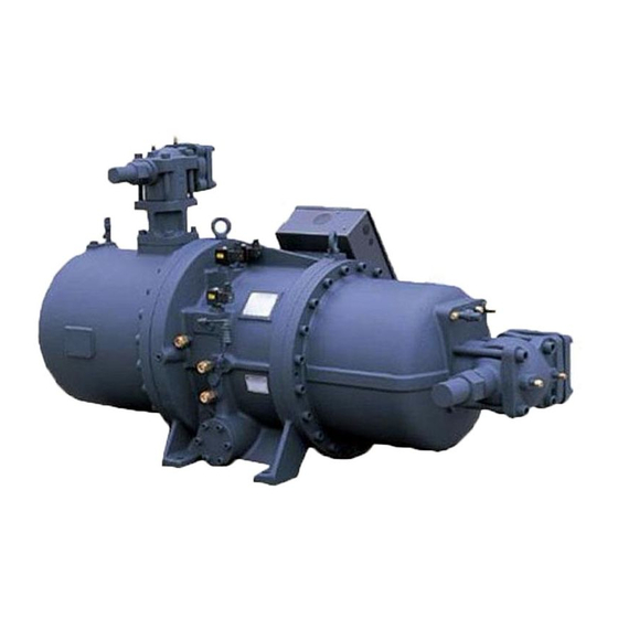
2.4 Compressor outline Low voltage compressor outline RT-120~140(E,T)/RT-111 (motor A&B) Vol. 2.6 © 2020 Hanbell Precise Machinery Co., Ltd. All rights reserved... - Page 11 High voltage compressor outline RT-120~140(E,T)/RT-111 (motor A) Vol. 2.6 © 2020 Hanbell Precise Machinery Co., Ltd. All rights reserved...
- Page 12 High voltage compressor outline RT-120~140(E,T)/RT-111 (motor B) Vol. 2.6 © 2020 Hanbell Precise Machinery Co., Ltd. All rights reserved...
- Page 13 Low voltage compressor outline RT-160~200(E,T)/RT-221 (motor A) Vol. 2.6 © 2020 Hanbell Precise Machinery Co., Ltd. All rights reserved...
- Page 14 High voltage compressor outline RT-160(T)(motor B) Vol. 2.6 © 2020 Hanbell Precise Machinery Co., Ltd. All rights reserved...
- Page 15 Low voltage compressor outline RT-160(T)(motor B) Vol. 2.6 © 2020 Hanbell Precise Machinery Co., Ltd. All rights reserved...
- Page 16 Low voltage compressor outline RT-180(T),RT-161(60Hz) (motor B) Vol. 2.6 © 2020 Hanbell Precise Machinery Co., Ltd. All rights reserved...
- Page 17 Low voltage compressor outline RT-180~200(T),RT-161(50Hz) (motor B) Vol. 2.6 © 2020 Hanbell Precise Machinery Co., Ltd. All rights reserved...
- Page 18 High voltage compressor outline RT-180~200(T),RT-161(50/60Hz) (motor B) Vol. 2.6 © 2020 Hanbell Precise Machinery Co., Ltd. All rights reserved...
- Page 19 Low voltage compressor outline RT-200(T) (60Hz) (motor B) Vol. 2.6 © 2020 Hanbell Precise Machinery Co., Ltd. All rights reserved...
- Page 20 High voltage compressor outline RT-202,RT-221 (50/60Hz) (motor A) Vol. 2.6 © 2020 Hanbell Precise Machinery Co., Ltd. All rights reserved...
- Page 21 High voltage compressor outline RT-202,RT-221 (50/60Hz) (motor B) Vol. 2.6 © 2020 Hanbell Precise Machinery Co., Ltd. All rights reserved...
- Page 22 Low voltage compressor outline RT-221 (50Hz) (motor A) Vol. 2.6 © 2020 Hanbell Precise Machinery Co., Ltd. All rights reserved...
- Page 23 Low voltage compressor outline RT-221 (60Hz) (motor A) Vol. 2.6 © 2020 Hanbell Precise Machinery Co., Ltd. All rights reserved...
- Page 24 Low voltage compressor outline RT-240~280 (50Hz) (motor A) Vol. 2.6 © 2020 Hanbell Precise Machinery Co., Ltd. All rights reserved...
- Page 25 High voltage compressor outline RT-240~280 (50/60Hz) (motor A) Vol. 2.6 © 2020 Hanbell Precise Machinery Co., Ltd. All rights reserved...
- Page 26 High voltage compressor outline RT-240~280 (50/60Hz) (motor B) Vol. 2.6 © 2020 Hanbell Precise Machinery Co., Ltd. All rights reserved...
- Page 27 Low voltage compressor outline RT-240 (60Hz) (motor A) Vol. 2.6 © 2020 Hanbell Precise Machinery Co., Ltd. All rights reserved...
- Page 28 Low voltage compressor outline RT-260~280 (60Hz) (motor A) Vol. 2.6 © 2020 Hanbell Precise Machinery Co., Ltd. All rights reserved...
-
Page 29: Connections
Flow velocity in the discharge side of the compressor could be as high as 15~20m/sec. High-speed discharge gas will make noise in discharge connection. In order to decrease the noise level, it’s recommended to round sharp edges of joints of piping. Vol. 2.6 © 2020 Hanbell Precise Machinery Co., Ltd. All rights reserved... - Page 30 1.Density & volume flow operation condition: water-cooling machine CT/ET=36/6℃, Heat pump ※ CT/ET=46/6℃ . 2.Install the butterfly valve close to the condenser inlet end. ※ Figure 2.2.1 Outline of butterfly valve Vol. 2.6 © 2020 Hanbell Precise Machinery Co., Ltd. All rights reserved...
- Page 31 ※The butterfly valve is of wafer type butterfly valve and installed in between ANSI class 150 flanges. Table 2.5.1 Specifications of flange Figure 2.3 Discharge and suction piping Caution: Residue from welding might damage the compressor seriously. Vol. 2.6 © 2020 Hanbell Precise Machinery Co., Ltd. All rights reserved...
- Page 32 Thus, please follow the instructions on compressor mounting (refer to 6.2 Installation and fixation of the compressor) and the advice of using flange connections. Vol. 2.6 © 2020 Hanbell Precise Machinery Co., Ltd. All rights reserved...
-
Page 33: Size Of Bushings For Motor Liquid Injection
Table 2.6 Dimensions of bushings Note:To effectively control motor temperature, some service valve can be installed in the piping before the bushing for motor liquid injection to provide adequate amount. Vol. 2.6 © 2020 Hanbell Precise Machinery Co., Ltd. All rights reserved... -
Page 34: Compressor Structure
Oil return flange Sight glass (refrigerant level) Gas return pipe Power bolt Inlet flange for motor cooling Oil return connection Outlet flange for motor cooling Oil pump Actuator Vol. 2.6 © 2020 Hanbell Precise Machinery Co., Ltd. All rights reserved... -
Page 35: Chapter 3. Capacity Control System
Figure 3.1 Inlet guide vanes in the compressor Figure 3.1 Compressor inlet As illustrated in Figure 3.1, RT series standard water-cooled compressors have first inlet guide van (IGV1). Refrigerant gas from the evaporator outlet flows through the suction nozzle to the compressor suction inlet. After the inlet nozzle, gas flow velocity increases due to the narrow passage. - Page 36 Figure 3.2.1 Refrigerant cycle diagram with economizer contributes to higher efficiency and this is due to an approximately 7% capacity gain occurs between point 5 & point 6. Vol. 2.6 © 2020 Hanbell Precise Machinery Co., Ltd. All rights reserved...
-
Page 37: Control Of Inlet Guide Vanes
5%. Min. mass flow Figure Figure3.3CloseInlet guide vanes completely Vol. 2.6 © 2020 Hanbell Precise Machinery Co., Ltd. All rights reserved Vol. 2.6 © 2020 Hanbell Precise Machinery Co., Ltd. All rights reserved... -
Page 38: Vane Actuator Control
3.2.2 Proportional control board setting The following picture is the appearance of the proportional board. All settings have been completed in the factory. Please contact technicians from Hanbell for special setting requirements. :Only authorized and certified technicians are allowed to change the settings. -
Page 39: Digital Bcd Switch Setting
User can select input signal type by adjusting DIP switches as follows: Note:Actuator IGV1: terminal #15(+ve),terminal #16(-ve);Actuator IGV2: terminal #10(+ve),terminal #11(-ve). :Do not adjust DIP switch when power is supplied to the actuator! Caution Vol. 2.6 © 2020 Hanbell Precise Machinery Co., Ltd. All rights reserved... - Page 40 When using 4 ~ 20mA as the input signal, if the dead band value (sensitivity) is set to 1%, the input current changes need to be over 16/100 = 0.16mA to make a 1% movement. Vol. 2.6 © 2020 Hanbell Precise Machinery Co., Ltd. All rights reserved...
-
Page 41: Duty Cycle
30 seconds can be used. :In order to prevent accumulated heating of the motor due to frequent operations, it Caution is advisable to set the start frequency to maximum 3 times/minute. Vol. 2.6 © 2020 Hanbell Precise Machinery Co., Ltd. All rights reserved... -
Page 42: Wiring
:Please turn off all power services before attempting to perform maintenance and Caution wiring of actuator. Before dismantling the actuator, make sure that the IGV is in fully close and not pressurized condition. Vol. 2.6 © 2020 Hanbell Precise Machinery Co., Ltd. All rights reserved... - Page 43 :It is required to install 2A fuse at the input end of the main power source to protect Caution the actuator. Vol. 2.6 © 2020 Hanbell Precise Machinery Co., Ltd. All rights reserved...
-
Page 44: Led Indicator Lights
Flickering Error indicator for one of the Yellow light following situations : No input signal; 4-20 mA polarity error; Reversal of equipotential line. Table 3.2.6 LED Indicator lights Vol. 2.6 © 2020 Hanbell Precise Machinery Co., Ltd. All rights reserved... -
Page 45: Manual Operation
Check board for damage. Verify input signal. Current / IGV position Check DIP switch configuration. converter Check board for damage. Table 3.2.9 Actuator troubleshooting 3.2.10 Actuator capacity control Vol. 2.6 © 2020 Hanbell Precise Machinery Co., Ltd. All rights reserved... -
Page 46: Surge And Stall Phenomenon
Figure 3.5, when compressor operates above the surge line, stalling or surging may occur. When surging occurs, the discharge pressure of compressor will reduce drastically, lower than the Vol. 2.6 © 2020 Hanbell Precise Machinery Co., Ltd. All rights reserved... - Page 47 15 seconds (except during loading control of the compressor). Please refer to section 3.3.1 for surge protection strategy (mechanism). Note:RT series compressors use rigid bearings and are capable of withstanding short-term surge up to 15 seconds. However, the compressor cannot withstand long-term surge, thus using only current detection for surge protection is not allowed.
-
Page 48: Fixed-Frequency Capacity Control And Surge Protection Strategy
Pr=pressure ratio (safety margin line) =y=a+bx+cx Where a, b, c, d, e are constants and x is the IGV opening. Vol. 2.6 © 2020 Hanbell Precise Machinery Co., Ltd. All rights reserved... - Page 49 Warning: : : : Safety margin line formula is the primary protection of compressor surge, DO NOT use current detection only for surge protection as it only passively activated when surge occurs. Compressor will be seriously damaged by repeating occurrence of surge. Vol. 2.6 © 2020 Hanbell Precise Machinery Co., Ltd. All rights reserved...
-
Page 50: Energy Savings With Variable Frequency Compressor
Dual IGV relationship for different models Both RT series and heat pump are equipped with double IGV mechanism. The actuators are set up separately while the operations of IGV1 and IGV2 are coupled. The formula is as follows: 1.When 100≧IGV1≧70,IGV2=100 Model 2.When 70>IGV1>0,... - Page 51 IGVs so that IGV opening can be decreased. As the cooling load continues to drop, speed signal from the compressor continues to turn off the guide vanes and increase motor rotational speed. Vol. 2.6 © 2020 Hanbell Precise Machinery Co., Ltd. All rights reserved...
- Page 52 Finally, insert the pressure ratio based the estimated pressures and IGV=10% into the formula to calculate the minimum operable frequency+1Hz; otherwise start-up with the highest operating frequency. Vol. 2.6 © 2020 Hanbell Precise Machinery Co., Ltd. All rights reserved...
- Page 53 Excessively low speed will cause inefficient discharge of motor cooling liquid, oil leakage and bearing slippage due to low loading, in extreme cases, can lead to catastrophic failure of compressor. Figure 3.7 A schematic diagram of inverter operating range Vol. 2.6 © 2020 Hanbell Precise Machinery Co., Ltd. All rights reserved...
- Page 54 Target chilled water temperature (CHWT), 7℃ <6.8℃ >7.5℃ 6.5~6.8℃ 6.8~7.2℃ 7.2~7.5℃ Range Loading mode fast unloading normal unloading Neutral zone normal loading fast loading Inverter output -1Hz -0.5Hz no action +0.5Hz +1Hz Vol. 2.6 © 2020 Hanbell Precise Machinery Co., Ltd. All rights reserved...
-
Page 55: Hot Gas Bypass (Hgbp)
50%, and end user needs 20%. The pipe diameter and flow need to be considered based on the 30% difference. Figure 3.7 Refrigerant Circuit & Motor Cooling systems Vol. 2.6 © 2020 Hanbell Precise Machinery Co., Ltd. All rights reserved... - Page 56 Note: 1. For dual IGV models, intermediate inlet is less likely to have liquid absorption issue, thus the minimum operating opening is ≥5%. The link relationship between IGV1 and IGV2 should be applied by Hanbell to ensure that the compressor intermediate pressure control is at the best point.
- Page 57 7.08 bar Pm=intermediate pressure 2. RT-161,221 When IGV>0, 1.025*(IGV%/IGV100%)^0.035*(Pe*Pc)^0.5+Pe/Pc*0.55 When IGV=0, 1.025*0.9*(Pe*Pc)^0.5+Pe/Pc*0.55 E.g., 3.62 bar where, 11.9 bar Pe=evaporator pressure IGV= 50 % Pc=condenser pressure 6.74 bar Pm=intermediate pressure Vol. 2.6 © 2020 Hanbell Precise Machinery Co., Ltd. All rights reserved...
-
Page 58: Chapter 4. Lubrication System
Oil filter is the only component in the pipeline that has variable resistance while the rests are constants, thus the pressure difference of P1-P2 should be monitored to prevent lack of lubrication caused by oil filter blockage. Vol. 2.6 © 2020 Hanbell Precise Machinery Co., Ltd. All rights reserved... -
Page 59: Oil Pump
(R2) and provides adequate flow rate of oil. Compressor internal resistance (R2) protection Hanbell RT-series centrifugal compressor has been tested and verified that the optimum flow rate of oil is 20~25L/min. in the form of oil-jet and ensures the bearing outer ring temperature to be less than 80°C after cooling. -
Page 60: Oil Cooler
3/4HP oil pump (@60Hz). Please contact Hanbell technicians for other specification configuration requirements. 2. Bearings used by RT series compressor require stable supply of lubricant. 3. Before / after compressor start-up, the start-up and shut down of oil pump must be advanced and delayed by 3 seconds to provide sufficient lubrication. -
Page 61: External Oil Filter
The filter shell should be able to withstand oil pressure as high as 12 to 15 bars. Hanbell external oil filter must be used. Its filtering material could be cellulose (paper) or synthetic fiber (15~25μm). Paper can withstand flow of high-pressured oil without being torn apart. -
Page 62: Oil & Refrigerant Circuits
Figure 4.3. Power of ejection comes from high pressure in the condenser or middle pressure in the economizer. Note:RT series compressors are equipped with ball and radial bearings. Therefore, the amount of lubricant need is much lesser. This design minimizes possibility of oil leakage to the system. -
Page 63: Oil Temperature Control In The Oil Tank
Note2: There are oil separators installed for effective oil separation at oil return and refrigerant return ports in RT series compressors. Please refer to item 13&14 in Figure 4.4. Besides, gears are installed in the gear casing to efficiently minimize fluctuation of oil level due to high-speed rotation. - Page 64 Note: If ambient temperature is low, it is recommended to turn on refrigerant heaters turn on refrigerant heaters during stop of compressors. Vol. 2.6 © 2020 Hanbell Precise Machinery Co., Ltd. All rights reserved Vol. 2.6 © 2020 Hanbell Precise Machinery Co., Ltd. All rights reserved...
- Page 65 Figure 4.6 Labyrinth ring RT series compressors are equipped with rigid bearings and fine oil separators. Therefore, oil carry-over in the system is much less. For oil return from the evaporator, orifice size of the oil return outlet of the evaporator should be confined. Suggested orifice sizes are shown as the table as below.
-
Page 66: Lubricants
The main functions of lubricant in the centrifugal compressor are lubrication and cooling. Bearings used in RT series compressors require a small but steady volume of oil for lubrication. Please pay more attention to oil temperature which is crucial to compressor bearing life. - Page 67 Middle and Low, oil return must be done or oil charge must be replenished; else if the level is lower than Low, the compressor must be stopped emergently to prevent dry wear of oil pump and bearing failure. Vol. 2.6 © 2020 Hanbell Precise Machinery Co., Ltd. All rights reserved...
-
Page 68: Oil Change
Only trained technicians are allowed to finish the maintenance work. Any proper service requirement, please contact HANBELL technicians. Vol. 2.6 © 2020 Hanbell Precise Machinery Co., Ltd. All rights reserved... -
Page 69: Chapter 5. Motor
Chapter 5. Motor 5.1 Motor cooling The motor in RT series compressor is cooled by liquid refrigerant that comes from the condenser. Solenoid valves, expansion valves, or orifices should be installed on piping before the suction flange as a throttle for inflow control. In order to keep the motor temperature between30~90℃, it is estimated that heat exchange is equal to around 6~10%... - Page 70 Protector connect method: 1 & 2 are PTC protector contact, A & B are concurrent, O1 is contact for 2 pairs of Pt100, C& D are concurrent, O2 is contact for the other 2 pairs of Pt100. Vol. 2.6 © 2020 Hanbell Precise Machinery Co., Ltd. All rights reserved...
- Page 71 Insulation test voltage U is – AC 1.5kV Figure 5.5 Pt1000 sensor Please specify Pt100 or Pt1000 sensors when placing orders to Hanbell. In addition, all models can be equipped with Pt100 or Pt1000 sensors to precisely measure motor coil temperatures for control of motor cooling.
-
Page 72: Motor Protector
5.2 Motor protector In order to protect the compressors, the RT series compressors have been equipped with three PTC temperature sensors on the motor coil. The temperature sensors can be connected to the INT69HBY temperature control module to monitor the temperature change of the motor coil. - Page 73 3. The lockout can be cancelled by main reset of approx. 5 seconds (disconnect L-N) Note: In order to make sure phase loss and phase sequence protection function well, please connect L1, L2, and L3 to the motor side as Figure5.6 shown. Vol. 2.6 © 2020 Hanbell Precise Machinery Co., Ltd. All rights reserved...
- Page 74 9. The relay is fed out as an N/O dry contact, which is closed under good conditions. 10. Sensor and supply circuits are galvanic isolated. 11. The motor protector is not suitable for application of frequency converters. Vol. 2.6 © 2020 Hanbell Precise Machinery Co., Ltd. All rights reserved...
-
Page 75: Electrical Data And Design
3. Acceleration of the motor rotor becomes smaller at full-load starting. Therefore compressors require starting at partial load (=Actuator 0%). ● Soft-start features 1. Starting current is 3 times higher of rated current ampere. Vol. 2.6 © 2020 Hanbell Precise Machinery Co., Ltd. All rights reserved... -
Page 76: Motor Design:direct On Line Start/Soft Start/Inverter Start
RT series compressors with high voltage motors can start by direct start as below shown. Figure 5.9 Wiring for high voltage RT series compressors with low voltage motors can start by Y-Δ start, soft start and inverter start as below shown. Figure 5.10 Wiring for low voltage Note: In case of soft start and inverter start, bridges must be installed for wring of the same phase to prevent current imbalance. - Page 77 When taking the low voltage cable entry, the magnetic induction produced among phases will cause heat to the wiring box. Both entrances are applicable for low voltage wiring. Vol. 2.6 © 2020 Hanbell Precise Machinery Co., Ltd. All rights reserved...
-
Page 78: Mcc & Lra
CT / ET = 40/13 ℃, the heating machine operating condition is about CT / ET = 52/14 ℃, a slightly different from the actual horsepower during the motor design. The actual Vol. 2.6 © 2020 Hanbell Precise Machinery Co., Ltd. All rights reserved... - Page 79 3.3kV 4.16kV 10kV 6.6kV 11kV 3.3kV 4.16kV 10kV 6.6kV RT-180(E,T) 11kV RT-161 3.3kV 4.16kV 10kV 6.6kV 11kV 3.3kV 4.16kV 10kV 6.6kV 11kV RT-200(E,T) 3.3kV 4.16kV 10kV 6.6kV 11kV Vol. 2.6 © 2020 Hanbell Precise Machinery Co., Ltd. All rights reserved...
-
Page 80: Grounding
For security purpose, HANBELL strongly recommends to ensure the grounding during installation. Suggestion: a. Dedicated M12 grounding screw (instructed in terminal box) should be reliably connected with grounding wire. Vol. 2.6 © 2020 Hanbell Precise Machinery Co., Ltd. All rights reserved... -
Page 81: Insulation For High Voltage Main Terminals
1. LOCKTITE Cleaning liquid 2. 3MSCOTCHFIL gray electrical insulation materials 3. 3MSCOTCHKOTE paints 4. Plastic insulation tapes HANBELL will not provide the materials above because all of them can be sourced locally. Steps: 1. Shut down the power of the compressor. -
Page 82: 7Protective Measures Of Electric Shock
Between motor casing and ground, resistance = 0Ω, potential difference = 0V. Between device casing and ground, resistance = 0Ω, potential difference = 0V. Between drive and device casing, resistance = 0Ω, potential difference = 0V. Vol. 2.6 © 2020 Hanbell Precise Machinery Co., Ltd. All rights reserved... -
Page 83: Compressor Electrical And Safety Practices
5.4.2 The Inspection and Preparation before Electrical Wiring 5.4.2.1 Inspection of Unpacking All compressors have been passed the strict test by Hanbell. Users are unauthorized to disassemble to inspection, if necessary, please contact Hanbell Company. -
Page 84: Cable Selection
The material of armature terminal is brass; therefore armature terminal cannot stand the weight of high voltage cable. Installer must apply external cable shelve or tension-ease device to stand the high voltage cable. HANBELL will not provide wiring terminals. Please choose wiring size of power supply under 1.25 safety margin of maximum load. -
Page 85: Making Of Cable End And The Connector
2. The specification of accessories must be the same with cable, no injury parts, no damping of insulation materials, and sealing materials must work. Assemble Vol. 2.6 © 2020 Hanbell Precise Machinery Co., Ltd. All rights reserved... - Page 86 2892.5 8.367 400.5 3560 13.300 4005 21.150 700~2000 355~1016 4450 Table 5.2 Pull-out force of crimped connections Note: Refer to UL-486A for pull-out force standard of crimped connections. Vol. 2.6 © 2020 Hanbell Precise Machinery Co., Ltd. All rights reserved...
-
Page 87: Limitation Of Power Supply
●Unequal impedance in conductors of power supply wiring ●Unbalanced distribution of single phase load, such as lighting A 3-phase unbalanced voltage protector is an optional accessory. Please contact Hanbell for more details. Vol. 2.6 © 2020 Hanbell Precise Machinery Co., Ltd. All rights reserved... -
Page 88: Chapter 6 Compressor Lifting And Installation
Each HANBELL centrifugal compressor has been fully tested at the factory and all precautionary measures have been taken to make sure the compressor is in perfect condition during working. - Page 89 (as figure 6.3) to prevent pressure loss of liquid return, Note2: Compressor fixed bolts are required for 2 side of compressor. The middle one is not necessary. Vol. 2.6 © 2020 Hanbell Precise Machinery Co., Ltd. All rights reserved...
-
Page 90: Compressor Protection Device
And set up the guiding light on control box. Turning on the compressor at shorted circuit to bypass protection module is not allowed, and Hanbell is not responsible for the damage. Vol. 2.6 © 2020 Hanbell Precise Machinery Co., Ltd. All rights reserved... -
Page 91: Compressor Accessories
If any optional accessory is required and out of above mentioned standard accessories, please contact Hanbell for detailed specification and quotation. Vol. 2.6 © 2020 Hanbell Precise Machinery Co., Ltd. All rights reserved... -
Page 92: Operation And Maintenance
3. Actuator starting point is set to be 5% (for start-up program). 4. Hot gas bypass valve: check if movement from 0% ~ 100% is normal. Vol. 2.6 © 2020 Hanbell Precise Machinery Co., Ltd. All rights reserved... - Page 93 2.Verify if the compressor motor stops rotating within 30 seconds; if not, please check whether pressure ratio is a little higher and adjust opening of the hot gas bypass valve as reference. Vol. 2.6 © 2020 Hanbell Precise Machinery Co., Ltd. All rights reserved...
-
Page 94: Compressor Control Logic
1℃ comparing to saturated evaporating temperature. 6. Contact HANBELL or the local distributor if any abnormal vibration or noise is found at pipeline while the compressor is running. 7. Regularly check the chiller according to national regulations and the following items... - Page 95 (shutdown) 7. Time Zone 10-11: Pump Delay 3seconds shutdown area 8. Time Zone 11-12: Lower the Actuator (IGV1) opening to 5% while IGV2 is closed to 5% position Vol. 2.6 © 2020 Hanbell Precise Machinery Co., Ltd. All rights reserved...
-
Page 96: Troubleshooting
Improper system piping Check the oil pump Check leakage. Charge additional Lack of refrigerant Low suction refrigerant. pressure malfunction of the expansion valve Check and reset for proper superheat Note: Vol. 2.6 © 2020 Hanbell Precise Machinery Co., Ltd. All rights reserved... - Page 97 (below 5 torr) and then charge nitrogen to positive pressure (within 8 hours, it cannot increase above 1.33torr ) to ensure remain of refrigerant in the system to the minimum. Vol. 2.6 © 2020 Hanbell Precise Machinery Co., Ltd. All rights reserved...
-
Page 98: Compressor Vibration Measuring Point
6.7Compressor vibration measuring point 1. Simple vibration measurement Motor rear parts:MV、MH & MA Vol. 2.6 © 2020 Hanbell Precise Machinery Co., Ltd. All rights reserved... - Page 99 Gear Proximal parts:CIV、CIH、CIA Vol. 2.6 © 2020 Hanbell Precise Machinery Co., Ltd. All rights reserved...
- Page 100 2.Spectrum measurement:Please contact service technicians for spectrum measurement settings. Besides simple vibration meter point 6, additional measurement of the gear part distal: COV, COH, COA is necessary. Vol. 2.6 © 2020 Hanbell Precise Machinery Co., Ltd. All rights reserved...
Need help?
Do you have a question about the RT Series and is the answer not in the manual?
Questions and answers