Table of Contents
Advertisement
Quick Links
INSTALLATION & START-UP GUIDE
WARNING!
NO OIL
is shipped in compressor.
Compressor must
These Safeties ARE Required at Startup to Maintain Hanbell Warranty
a) Motor Module Trip (INT69HBY): Open for 1 second
b)
Low Oil Level Float Trip: Open for 30-60 seconds
c)
Unsafe Suction: Less than 5 psi for 3 seconds
d)
Low Differential Pressure: Less than 65 psi for 60 seconds (Oil Psi – Suction Psi)
e)
Unsafe Differential Pressure: Less than 35 psi for 5 seconds (Oil Psi – Suction Psi)
f)
Low Discharge Superheat: Less than 25°F for 300 seconds
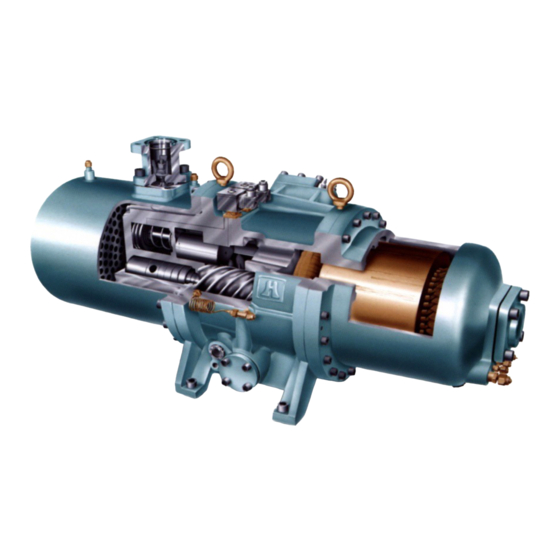
HANBELL COMPRESSOR
RC2-100 TO RC2-930
NEVER
be run backwards.
Rev M.5.2
Revision – 10/02/19
Advertisement
Table of Contents

Subscribe to Our Youtube Channel
Related Manuals for Hanbell RC2-100


Summary of Contents for Hanbell RC2-100
- Page 1 Compressor must NEVER be run backwards. These Safeties ARE Required at Startup to Maintain Hanbell Warranty a) Motor Module Trip (INT69HBY): Open for 1 second Low Oil Level Float Trip: Open for 30-60 seconds Unsafe Suction: Less than 5 psi for 3 seconds Low Differential Pressure: Less than 65 psi for 60 seconds (Oil Psi –...
- Page 2 Added Hanbell Compressor Picture Update Manual to REV J Updated Hanbell Liquid Injection Piping 05/24/13 M. Schreiber Added Hanbell Flooded Type Compressor with Oil Separator Update Manual to REV K 06/13/13 M. Schreiber Updated Hanbell Liquid Injection Piping Update Manual to Rev L Updated wiring of electrical power terminals K.
-
Page 3: Table Of Contents
Electrical Wiring ............................... 20 Pre-Start-up Procedure ............................ 21 Start-up Procedure ............................25 Recommended Safety Settings ........................25 Hanbell with VFD ............................. 26 Solenoids ................................ 27 Slide Amp Calculation............................34 Handling POE Oil Information .......................... 39 Warranty / Maintenance Information ........................ 40... -
Page 4: Compressor Crate Unpacking & Inspection
COMPRESSOR INSTALLATION & START-UP GUIDE REVISION M 1. Compressor Crate Unpacking & Inspection 1.1. Inspect crate and compressor for any shipping damage. 1.2. The compressor is in an easy open crate, cut straps and lift off crate top from base. 1.3. -
Page 5: Compressor Safety Instructions
When adding or doing a complete change, use only the listed Hanbell approved oils. POE oils readily absorb moisture and cause acid formation in the system. Keep oil exposure to the atmosphere to a minimum. -
Page 6: Recommended Liquid Injection Piping
COMPRESSOR INSTALLATION & START-UP GUIDE REVISION M 3.6. Liquid Injection Solenoid Valve and Expansion Valve (Required, Not included with compressor): The liquid injection system may be piped, but it is necessary to consider the required space for adjustment of the expansion valve while testing or running the compressor. -
Page 7: Screw Compressor Wiring Procedures
COMPRESSOR INSTALLATION & START-UP GUIDE REVISION M 5. Screw Compressor Wiring Procedures Following the diagrams below will prevent damage to the electrical terminals and the possibility of personal injury. - Page 8 COMPRESSOR INSTALLATION & START-UP GUIDE REVISION M Terminal The method to tell the terminals (V-Phase) By alphabet: Refer to the alphabet beside each terminal bolt in a star-delta motor. By numbers: Refer to the number beside each bolt in a PWS motor.
- Page 9 COMPRESSOR INSTALLATION & START-UP GUIDE REVISION M Figure 5-A Motor Wiring...
- Page 10 REVISION M 5.1. Electrical Power Terminals The power terminals of Hanbell compressors are made from ceramic materials and well insulated more than 1000MΩ. Be careful connecting the wiring and follow the list below. ⇒ The ceramic part on the power terminal should not be tighten by hitting otherwise the insulation of the power terminal could be degraded.
- Page 11 COMPRESSOR INSTALLATION & START-UP GUIDE REVISION M 5.2. Across the Line Jumper Bar Installation Photo shows extra nuts installed under jumper bar for clearance of power bolt Insulation. Connect line voltage directly on Terminal post.
-
Page 12: Int69Hby
REVISION M 6. Description - INT69HBY DIAGNOSE Hanbell supplies INT69 HBY Diagnose for motor protection with monitoring functions of phase loss, phase sequence, motor temperature, and discharge temperature. The module has built in flash codes that are help- ful for diagnosing safety faults. - Page 13 COMPRESSOR INSTALLATION & START-UP GUIDE REVISION M Flash Code Overview Green lit Compressor Operational Green flashing Compressor Running Red/Orange flashing Error, Compressor is switched off; for description see table below flashing sequence flashing sequence Description (Red LED) (Orange LED) Motor temperature; Static switch off, Permissible winding tempera- ture exceeded...
- Page 14 COMPRESSOR INSTALLATION & START-UP GUIDE REVISION M How to Wire INT69HBY Diagnose The following diagram shows the proper wiring connections for the module. The module is connected to L1, L2 and L3 for phase monitoring. Stake on connectors at terminal “A” are connected in series with the discharge PTC and wired back to S1 and S2.
- Page 15 COMPRESSOR INSTALLATION & START-UP GUIDE REVISION M...
- Page 16 COMPRESSOR INSTALLATION & START-UP GUIDE REVISION M...
- Page 17 COMPRESSOR INSTALLATION & START-UP GUIDE REVISION M...
-
Page 18: Maintenance Area Requirement
COMPRESSOR INSTALLATION & START-UP GUIDE REVISION M 7. Maintenance Area Requirement Please refer to the below tables for recommended minimum space requirements RC2-100 RC2-140 RC2-180 RC2-170 RC2-200 RC2-230 RC2-260 RC2-300 A.(cm) 5.9” (15) 16.1” (41) 18.1” (46) 18.5” (47) 20.1” (51) B.Outwards(cm) - Page 19 (air-cooled or water-cooled), refrigerant, and lubricant (synthetic or mineral). Replacement of piston rings and bearings should be performed by Hanbell authorized technicians. When counts of piston loading and unloading motion are higher than 10,000 times, piston rings should be replaced immediately.
-
Page 20: Compressor Piping
(standard size for copper piping, if 8.2. The welding for the compressor should connecting to steel piping contact your Hanbell contain at least 15% Argentina as an representative) After welding the flanges and ingredient. Once all piping is completed,... -
Page 21: Pre-Start-Up Procedure
RC2-320 clockwise. RC2-340 Pre-Start-up Procedure RC2-370 Oil Charging: Only lubricants listed in Hanbell’s 9.1. Technical Manual are to be used. SUBSTITUTES. RC2-410 Make sure the oil level is to the middle of the high RC2-470... - Page 22 COMPRESSOR INSTALLATION & START-UP GUIDE REVISION M Note: For other applicable oil types, please consult with HANBELL first for approval...
- Page 23 Please follow the piping diagram below. Please ensure there is oil charged in the piping feeding the compressor to avoid a dry start-up. HANBELL FLOODED TYPE WITH OIL SEPARATOR...
- Page 24 COMPRESSOR INSTALLATION & START-UP GUIDE REVISION M HANBELL FLOODED TYPE WITH OIL SEPARATOR & OIL COOLER In the lubricant circuit, installing the oil solenoid valve in the proper place is very important. As the compressor is shut down, lubricant will automatically inject into the compressor due to pressure differential. It will easily make the system difficult to restart because of low oil level or lubricant injection inside the compressor chamber.
-
Page 25: Start-Up Procedure
Recheck oil level. The oil level should be to the middle of the high side sight glass. • Hanbell recommends suction superheat 10°F to 20°F, discharge superheat 30°F and a pressure differential of at least 70 psig. 11. Recommended Safety Settings •... -
Page 26: Hanbell With Vfd
COMPRESSOR INSTALLATION & START-UP GUIDE REVISION M 12. Hanbell with VFD 12.1. Wiring & Controls Set Up • For a new installation, DO NOT CONNECT the L1, L2, and L3 Red, White and Blue wires to the INT69HBY motor module. -
Page 27: Solenoids
COMPRESSOR INSTALLATION & START-UP GUIDE REVISION M Solenoids 13.1. Solenoid Identification (Normally Open / Normally Closed) NORMALLY OPEN SOLENOID NORMALLY CLOSED SOLENOID CAN BE IDENTIFIED BY NOTCHES ON NUT THERE ARE NO NOTCHES ON THE NUT... - Page 28 COMPRESSOR INSTALLATION & START-UP GUIDE REVISION M 13.2. Infinite Capacity (Stepless) Minimum (50-100%) UNLOAD LOAD START UNLOAD...
- Page 29 COMPRESSOR INSTALLATION & START-UP GUIDE REVISION M 13.3. Step Load 50%, 75%, 100% (Blank Off Cap) LOAD (Load Cap) 13.4. Step Load 25% 50%, 75% & 100% (Only 25% at Start-Up and Shut-Down) Please see APP Note 76 for Step Loading Instruction Kit...
- Page 30 COMPRESSOR INSTALLATION & START-UP GUIDE REVISION M 13.5. Solenoid Alignment IMPORTANT SOLENOID ALIGNMENT IS CRITICAL TO PROPER FUNCTIONING OF COMPRESSOR WHEN INSTALLING SOLENOIDS ON THE WHEN INSTALLING A LOAD CAP, MAKE COMPRESSOR, ENSURE THAT THE HOLES SURE THAT THE CIRCULAR HOLE IN THE MATCH FOR PROPER OIL FLOW TO GASKET COVERS...
- Page 31 COMPRESSOR INSTALLATION & START-UP GUIDE REVISION M ALSO MAKE SURE HOLES LINE UP IF INSTALLING ORIFICE PLATE (FOR COMPRESSORS MANUFACTURED BEFORE APRIL 2013) NOT ALL OIL FLOW HOLES ARE ORIENTED THE SAME WAY. BE SURE TO DOUBLE CHECK THAT THE SOLENOID HOLES LINE UP PROPERLY AS SHOWN BELOW.
- Page 32 COMPRESSOR INSTALLATION & START-UP GUIDE REVISION M PROPER INSTALLATION OF A SOLENOID PROPER INSTALLATION OF A SOLENOID WITH ORIFICE PLATE WITHOUT ORIFICE PLATE...
- Page 33 COMPRESSOR INSTALLATION & START-UP GUIDE REVISION M ATTENTION ORIFICE PLATES WERE REPLACED BY ORIFICE PLUGS IN COMPRESSORS MANUFACTURED AFTER APRIL 2013...
-
Page 34: Slide Amp Calculation
Slide Amp Calculation Adjustments through MCS-Connect If you are using MCS Controls with a Hanbell Infinite Control (stepless) compressor, you need to follow these steps when commissioning the compressor to ensure correct operation. Any questions regarding this release, contact: support@mcscontrols.com Micro Control Systems, Inc. - Page 35 Revision 02-15-2019 General Concept Not all compressors will run exactly at the full load amperage rating that the manufacturer provides. Likely it will be very close, but some fine tuning of the configuration will enable the operator to maximize efficiency and control of the unit.
- Page 36 Revision 02-15-2019 1. Setting the Lower Limit Now that you have finished calibrating the upper FLA% you may now work on setting the minimum FLA% limit. Begin by turning the LOAD relay manually OFF, and UNLOAD relay manually ON. Wait until the compressor is fully unloaded and then check the FLA% value in the circuit grid.
- Page 37 24 Month Warranty Suggestive Guidelines for Preventive Maintenance All HANBELL screw compressors are put through strict quality and performance testing prior to shipping from the factory. Provided that terms of payment are observed, a two year (24-month) warranty against factory defects is offered from the date of installation or 27 months from date of shipment.
- Page 38 6months to ensure the condition remains safe. In the case of being unable to do the oil analysis periodically, consult Hanbell oil change schedule because the interval of oil change varies by the oil type and compressor operating condition.
-
Page 39: Handling Poe Oil Information
Hanbell Maintenance Version 1.0 HANDLING POE OILS Please read as improper handling can cause compressor failure and void the compressor warranty. POE oils are more hygroscopic than mineral oils, so exposing POE oils to air will result in their absorbing moisture quicker than mineral oils. When POE oils are exposed to moisture and heat, they may react, forming acid that is harmful to the system. -
Page 40: Warranty / Maintenance Information
Hanbell Maintenance Version 1.0 24 Month Maintenance Records Suggestive Guidelines for Preventive Maintenance Company _________________________________________________________________________________ Technician ______________________________________ Phone ____________________________________ Site Information Installation Site Name _________________________________________________________________________ Unit Information - USE A SEPARATE SHEET FOR EACH COMPRESSOR Model Number Serial Number Type Oil Used... - Page 41 Warranty Start Up / Status Report Upon startup, please complete the form with as much detail as possible NOTE: DOWNLOAD FORM TO YOUR DESKTOP - FILL IN AND SAVE AS PDF Date email to sales@mcscontrols.com or print and fax to 239-694-0031 Sales Order # General Information Company...
Need help?
Do you have a question about the RC2-100 and is the answer not in the manual?
Questions and answers