Table of Contents
Advertisement
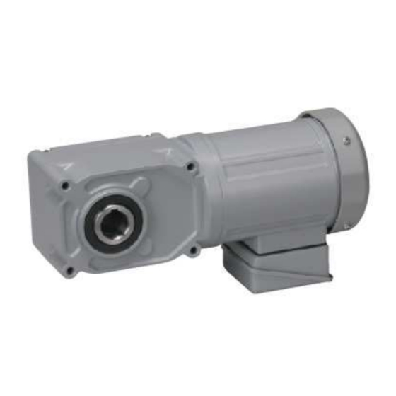
GTR eco SERIES(0.1kW〜2.2kW)
IPM gearmotor
Detailed Instruction Manual
<Please read this manual before using the product.>
Contents of this manual is based on using with our specialized inverter.
When operating with other inverters, make sure to check
「14. Notes on operating with inverters other than the specialized inverter」.
Nissei Corporation
Advertisement
Table of Contents


Need help?
Do you have a question about the GTR ECO Series and is the answer not in the manual?
Questions and answers