Table of Contents
Advertisement
Quick Links
Advertisement
Table of Contents

Related Manuals for TECO JN5-CM-PDP


Summary of Contents for TECO JN5-CM-PDP
- Page 1 2012.04 Apply to: JN5-CM-PDP...
-
Page 2: Table Of Contents
3 Communication ..........................9 3.1 Initial Power Up ........................9 3.2 PROFIBUS-DP Address ..................... 9 3.3 JN5-CM-PDP Cyclical Data Exchange ................9 3.3.1 PPO configuration ....................9 3.3.2 Extended configuration ..................10 3.3.3 Default settings of PZD structure ................10 ... -
Page 3: Summary
JN5-CM-PDP User Manual File No.:R09-PBUS-D20 Version:01 1 Summary JN5-CM-PDP module was developed for automation tasks using the PROFIBUS-DP field bus system. JN5-CM-PDP module is a “gateway” and can only be operated in combination with other base units. JN5-CM-PDP module can be connected with different type base units when selecting different GSD file. -
Page 4: Structure Of The Unit
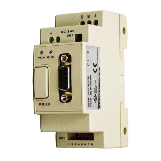
JN5-CM-PDP User Manual File No.:R09-PBUS-D20 Version:01 Structure of the Unit ① 24vDC power supply ② Retractable mounting feet ③ 2bits DIP switch (terminal resistor) ④ POW & BUS LED ⑤ PRESS ⑥ 8bits DIP switch (setting address ) ⑦ RS485 port (Interface to connect with A510) ⑧... -
Page 5: Installation
JN5-CM-PDP User Manual File No.:R09-PBUS-D20 Version:01 2 Installation 2.1 Installation and Dimension ● Installation JN5-CM-PDP module should always be mounted vertically. Press the slots on the back of the module onto the rail until the plastic clamps hold the rails in place. -
Page 6: Connecting Power Supply
JN5-CM-PDP User Manual File No.:R09-PBUS-D20 Version:01 ● Dimension: Unit: mm (1 inch = 25.4mm) 2.2 Connecting Power Supply JN5-CM-PDP module operates with a 24vDC supply voltage. User can use an external 24vDC power. ①: 1A quick-blowing fuse, circuit-breaker or circuit protector... -
Page 7: Connect With Base Unit And Setting Parameters
JN5-CM-PDP User Manual File No.:R09-PBUS-D20 Version:01 2.3 Connect with Base Unit and Setting Parameters JN5-CM-PDP module connected with base unit via a RS485 port with MODBUS RTU protocol. Setting for RS485 port: Baud Rate 19200kbps, 8 bit data length, 1bit for stop bit, and no parity bit. -
Page 8: Connect With Profibus-Dp Bus
JN5-CM-PDP User Manual File No.:R09-PBUS-D20 Version:01 2.4 Connect with PROFIBUS-DP Bus Please use a 9-pole D-SUB to connect the JN5-CM-PDP module to the PROFIBUS-DP field bus. For this use the special PROFIBUS-DP plug and the special PROFIBUS-DP cable. The type of cable used determines the permissible maximum bus length and the transfer rate. -
Page 9: Electronic Isolation
JN5-CM-PDP User Manual File No.:R09-PBUS-D20 Version:01 2.6 Electronic Isolation The following electrical isolation should be provided for the JN5-CM-PDP module: Note: Can’t use A510 user 24V to connect JN5-CM-PDP input, otherwise JN5-CM-PDP is no islanded with A510. 2.7 Data Transfer Rate and Distance... -
Page 10: Communication
JN5-CM-PDP User Manual File No.:R09-PBUS-D20 Version:01 3 Communication 3.1 Initial Power Up Before you power on the JN5-CM-PDP module, verify that it is properly connected to the power supply, to the bus connector and to the base unit. If the... -
Page 11: Extended Configuration
JN5-CM-PDP User Manual File No.:R09-PBUS-D20 Version:01 PKW: Parameter ID/value STW: Control word PZD: Process data ZSW: Status word PKE: Parameter ID HSW: Main set point IND: Sub-index HIW: Main actual value PWE: Parameter value NOTE: JN5-CM-PDP supports PPO1 and PPO3 structure only. -
Page 12: Control And Status Words
JN5-CM-PDP User Manual File No.:R09-PBUS-D20 Version:01 3.3.4 Control and Status words JN5-CM-PDP supports the PPO1 and PPO3 data structure. However, it does not support the bit assignments of control and status words in PROFIDrive profile. It only supports the A510 series drive control and status words. -
Page 13: Accessing Parameter Via Pkw Area
Bit 0 to 11 (PNU) contain the MODBUS address of the relevant parameter. Please refer to Appendix B: A510 series drive MODBUS address allocation. Bits 12 to 15(AK) contain the request or the response identifier. Request identifier (Master JN5-CM-PDP) Request Identifier Description No request Read parameter value... - Page 14 JN5-CM-PDP User Manual File No.:R09-PBUS-D20 Version:01 All parameters for the A510 series drive are 16-bit. A 16-bit parameter value is transferred by PWE2 (4th word). PWE1 (3rd word) must be set to 0 on the PROFIBUS-DP master in this case.
-
Page 15: Gsd File And Parameters
JN5-CM-PDP User Manual File No.:R09-PBUS-D20 Version:01 4 GSD File and Parameters A GSD file is a text file used to identify PROFIBUS-DP device (master or slave), which contains the necessary data for the configuration of DP slaves within a standard DP master. Typical information in a GSD file are Vendor information, supported Baud rates, Timing information, supported Options/features and Available I/O signals. - Page 16 JN5-CM-PDP User Manual File No.:R09-PBUS-D20 Version:01 The default parameter setting is shown as in the following:...
-
Page 17: Troubleshooting
JN5-CM-PDP User Manual File No.:R09-PBUS-D20 Version:01 5 Troubleshooting 5.1 LED Display POW LED and BUS LED are used to monitor the JN5-CM-PDP communication status. LED state Description Corrective Actions POWER LED No power Verify the power supply of JN5-CM-PDP unit. -
Page 18: Appendix
Software_Release = "V1.0" Redundancy Repeater_Ctrl_Sig 24V_Pins Implementation_Type = "SPC3" ;Bitmap_Device = "A510 DRV" ;Bitmap_Diag = "A510 DRV" ;Bitmap_SF = "A510 DRV" Slave_Family = 1@TECO@A510 ; Drives family ; Supported Communication Speeds: 9.6_supp 19.2_supp 93.75_supp 187.5_supp 500_supp 1.5M_supp 3M_supp 6M_supp 12M_supp... - Page 19 JN5-CM-PDP User Manual File No.:R09-PBUS-D20 Version:01 MaxTsdr_9.6 = 60 MaxTsdr_19.2 = 60 MaxTsdr_93.75 = 60 MaxTsdr_187.5 = 60 MaxTsdr_500 = 100 MaxTsdr_1.5M = 150 MaxTsdr_3M = 250 MaxTsdr_6M = 450 ;MaxTsdr_12M = 800 ; DP_Slave Information: Freeze_Mode_supp Sync_Mode_supp Auto_Baud_supp Set_Slave_Add_supp Min_Slave_Intervall ;...
- Page 20 Text(0) = "Stop DataExchange & Report Fault" Text(1) = "Continue & Report Alarm" Text(2) = "Ignore & Continue DataExchange" EndPrmText ExtUserPrmData = 1 "Dout 1: STW1(Master-> JN5-CM-PDP)" Unsigned16 0x2501 9473-9473 EndExtUserPrmData ExtUserPrmData = 2 "Dout 2: HSW" Unsigned16 0x2502 9474-9474 EndExtUserPrmData ExtUserPrmData = 3 "Dout 3: Not used"...
- Page 21 JN5-CM-PDP User Manual File No.:R09-PBUS-D20 Version:01 ExtUserPrmData = 6 "Din 2: HIW" Unsigned16 0x2524 9508-9508 EndExtUserPrmData ExtUserPrmData = 7 "Din 3: PZD3" Unsigned16 0x2522 9504-9519 EndExtUserPrmData ExtUserPrmData = 8 "Din 4: PZD4" Unsigned16 0x2527 9504-9519 EndExtUserPrmData ExtUserPrmData = 9 "LossDPComTreat"...
-
Page 22: Appendix B: A510 Modbus Address Allocation
JN5-CM-PDP User Manual File No.:R09-PBUS-D20 Version:01 Appendix B: A510 MODBUS address allocation Register Function Register Function Register Function Register Function Register Function Code Block Code Block Code Block Code Block Code Block Group00 Group01 Group02 Group03 Group04 0000H 00-00 0100H... - Page 23 JN5-CM-PDP User Manual File No.:R09-PBUS-D20 Version:01 Register Function Register Function Register Function Register Function Register Function Code Block Code Block Code Block Code Block Code Block 0325H 03-37 0326H 03-38 Group05 Group05 Group06 Group06 Group07 0500H 05-00 0518H 05-24 0600H...
- Page 24 JN5-CM-PDP User Manual File No.:R09-PBUS-D20 Version:01 Register Function Register Function Register Function Register Function Register Function Code Block Code Block Code Block Code Block Code Block 080CH 8 – 12 0902H 9 – 02 0A0CH 10 – 12 0B0CH 11 – 12 0B2AH 11– 42 080DH 8 –...
- Page 25 JN5-CM-PDP User Manual File No.:R09-PBUS-D20 Version:01 Register Function Register Function Register Function Register Function Register Function Code Block Code Block Code Block Code Block Code Block 0C15H 12 – 21 0C36H 12 – 54 1007H 16– 07 1107H 17 – 07 0C16H 12 –...
- Page 26 JN5-CM-PDP User Manual File No.:R09-PBUS-D20 Version:01 Command DATA (Readable and Writable) Register Content Operation signal Meaning Operation Command Stop Reverse Command Reverse Forward External Fault Fault (EFO) Fault Reset Reset Reserved Reserved Multi function Command S1 2501H Multi function Command S2...
- Page 27 JN5-CM-PDP User Manual File No.:R09-PBUS-D20 Version:01 Supervision Data (Only for reading) Register Content Meaning Operation State Stop Direction State Reverse Forward Inverter operation prepare state ready unready Abnormal Abnormal normal Data setting error Error No error ZeroSpeed Is440V 2520H FreqAgree...
- Page 28 JN5-CM-PDP User Manual File No.:R09-PBUS-D20 Version:01 External Fault 03 KeyKeypad Removedved External Fault 04 External Fault 05 External Fault 06 Modbus External Fault External Fault 07 Braking Transistor Fault External Fault 08 Braking Resistor Overheat External Fault 09 External Fault 10...
- Page 29 JN5-CM-PDP User Manual File No.:R09-PBUS-D20 Version:01 Supervision Data (Only for reading) Register Content MFIT state Meaning Terminal S1 Terminal S2 Terminal S3 Sequent Terminal S4 input 2522H value Terminal S5 Terminal S6 Terminal S7 Terminal S8 Terminal output (unused) 2523H...
Need help?
Do you have a question about the JN5-CM-PDP and is the answer not in the manual?
Questions and answers