Table of Contents
Advertisement
Quick Links
Advertisement
Table of Contents

Related Manuals for Zander Aachen MINOS SD1E


Summary of Contents for Zander Aachen MINOS SD1E
- Page 1 MINOS SD1E Operating Instructions Safety Relay MINOS SD1E...
- Page 2 Safety Relay MINOS SD1E H. Zander GmbH & Co. KG Am Gut Wolf 15 52070 Aachen, Germany info@zander-aachen.de www.zander-aachen.de Version: K11 E61-347-00 Engl. Translation of the original document Subject to technical modifications, no responsibility is accepted for the accuracy of this information.
-
Page 3: Table Of Contents
Safety Relay MINOS SD1E Contents 1. Scope ........................4 2. Target group ......................4 3. Safety instructions ....................4 4. Appropriate use ...................... 5 5. Disclaimer and warranty..................6 6. Features ......................... 7 7. Function ......................... 7 8. Application examples ..................... 9 9. -
Page 4: Scope
Safety Relay MINOS SD1E 1. Scope This document is valid for the following safety modules: • who are familiar with proper handling of the MINOS SD1E (Order-No.: 472841) safety components • who are familiar with the applicable EMC and ESD regulations 2. -
Page 5: Appropriate Use
Safety Relay MINOS SD1E 4. Appropriate use MINOS SD1E is a safety emergency stop relay for monitoring e.g. emergency stop Appropriate use also includes compliance buttons, safety doors and light curtains. The with: modules are also certified for operation in... -
Page 6: Disclaimer And Warranty
Safety Relay MINOS SD1E 5. Disclaimer and warranty If the above mentioned conditions for appro- This means that the connected load is priate use are not complied with or if the switched off as soon as a request from con-... -
Page 7: Features
Safety Relay MINOS SD1E 6. Features 7. Function • Config-Switches S1 and S2: Use up to PL e, Cat. 4, SILCL 3 At the back of the device are two slide- • Certified for operation in switches (S1 and S2) to configure the SD1E. - Page 8 Safety Relay MINOS SD1E Safe relay contact 13-14: Considering the start behaviour, the safe relay contact switches on at the time the safety circuit closes. Opening the safety circuit results in an immediate shutdown (safe condition). Fig. 1 Configurationtable SD1E...
-
Page 9: Application Examples
Safety Relay MINOS SD1E 8. Application examples Application example 1: Application example 2: SD1E for two-channel emergency-stop SD1E for single-channel emergency stop monitoring with short circuit monitoring and monitoring with automatic start up to monitored manual start up to PL e / SIL 3. - Page 10 Safety Relay MINOS SD1E Application example 3: Application example 4: SD1E for two-channel monitoring of a non- SD1E for dual channel safety door monitoring contact safety switch with short circuit moni- with manual start up to PL e / SIL 3.
- Page 11 Safety Relay MINOS SD1E Application example 5: Legend for all application examples: SD1E for two-channel monitoring of an E-Stop: Emergency stop button OSSD-Output, e.g. light curtain/grid and Start: Start button automatic start up to PL e / SIL 3 (cross : Positively driven contactors;...
-
Page 12: Mounting
Safety Relay MINOS SD1E 9. Mounting 10. Electrical connection • The device has to be installed in a cabinet Wiring and Config-Setting via the Config- having minimum protection class of IP54: Switches should only be carried out while • the voltage supply is switched off Mount on a 35 mm mounting rail as per •... -
Page 13: Commissioning
Safety Relay MINOS SD1E 4. Wiring the power supply ATTENTION!I Connect the power supply to the terminals A1 and A2 (see chapter 15 “Wiring / Applications If automatic start is configured, the - Power supply “). safe contact 13-14 immediately closes when the safety circuit is closing. -
Page 14: Checks And Maintenance
Safety Relay MINOS SD1E 12. Checks and maintenance The following checks are regularly required to ATTENTION: ensure proper and continuous functioning: • Proper operation is no longer Check the switching function guaranteed if the device is dam- • Check for signs of manipulation and safety aged, e.g. -
Page 15: Proof-Test
Safety Relay MINOS SD1E 13. Proof-Test To check the correct function of the device within the framework of a proof test, the following steps must be carried out: • Demand the safety function by opening the safety circuit. Check that the relay contact (13-14) opened by activation of the safety function. -
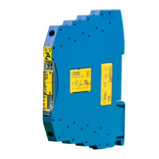
Page 16: Terminal Assignment And Led Displays
Safety Relay MINOS SD1E 14. Terminal assignment and LED display Power supply + DC 24 V Power Supply 0 V S21: Control line start Control line safety circuit 1 SD1E: Variant label Label - Upper terminal block Label - Lower terminal block... -
Page 17: Wiring / Applications
Safety Relay MINOS SD1E 15. Wiring / Applications Safety circuit Dual-channel emergency stop or safety door Depending on application or result of the risk monitoring with short circuit monitoring. assessment, e.g. according to EN ISO 13849- Up to PL e / SIL 3... - Page 18 Safety Relay MINOS SD1E Safety circuit Safety circuit Single-channel emergency stop or safety door Dual-channel monitoring of safe OSSD monitoring with earth fault monitoring. outputs with integrated cross circuit monitor- ing. Up to PL c / SIL 1 Up to PL e / SIL 3...
- Page 19 Safety Relay MINOS SD1E Safety circuit Start circuit Single-channel monitoring of safe OSSD Monitored manual start without feedback output. circuit. Note: Evaluation of the falling edge of the Up to PL e / SILCL 3 start signal (contact opens). Position Config-Switch S1: Disabled (Right) Position Config-Switch S2: Manual (Left) Fig.
- Page 20 Safety Relay MINOS SD1E Start circuit Start circuit Automatic start. Monitored manual start with feedback circuit. Note: Difference time monitoring at safety Note: Evaluation of the falling edge of the circuit in case of automatic start: start signal (contact opens).
- Page 21 Safety Relay MINOS SD1E Start behaviour Power supply Automatic start with feedback circuit. Power supply A1/A2. Note: Difference time monitoring at safety circuit in case of automatic start: Note: See chapter 10 “Electrical connection” I2 before I1: Difference time is arbitrary for further requirements of the power supply.
- Page 22 Safety Relay MINOS SD1E Safe relay contact Auxiliary output Safe relay contact suitable for different loads Suitable for indicator lamps or control inputs (see chapter 20 “ Technical Data - Safe relay of connected PLC controllers. contact”) with interference suppression.
- Page 23 Safety Relay MINOS SD1E...
-
Page 24: Time Diagrams
Safety Relay MINOS SD1E 16. Timing diagrams SD1E with automatic start Fig. 23 Timing diagram - SD1E with automatic start tE: Switch-on delay - typ. 10 ms tA: Switch-off delay - typ. 10 ms... - Page 25 Safety Relay MINOS SD1E SD1E with monitored manual start Fig. 24 Timing diagram - SD1E with monitored manual start tE: Switch-on delay - typ. 10 ms tA: Switch-off delay - typ. 10 ms...
-
Page 26: Monitoring Table
Safety Relay MINOS SD1E 17. Monitoring table If the device does not respond as expected, a monitoring can be carried out using the front LEDs according to the table below. LED off LED on: Explanation / Measure • Check the power supply - Power supply has to be within DC 24 V ±... - Page 27 Safety Relay MINOS SD1E LED off: LED on: Explanation / Measure Overvoltage at A1/A2: • Measure the supply voltage and adjust if necessary. Note! The maximum permissible supply voltage is DC 26.4 V The safe relay contact 13-14 is not enabled: •...
-
Page 28: Dimensions
Safety Relay MINOS SD1E 18. Dimensions 19. Safety parameters ATTENTION! • Once a year for applications up to PL d According to CNB / M / 11.050, a with Cat. 3 or SIL 2 with HFT = 1 request for the safety function is... - Page 29 Safety Relay MINOS SD1E Safety parameters according to EN ISO 13849-1 Conditions: AC-15: 5 A; Max. 10.000 Switching-Cycles / Year DC-13: 4 A; Max. 15.000 Switching-Cycles / Year Max. duration of use [Years] Category PFHd [1/h] 1.2E-08 Safety parameters according to IEC 61508 - High-Demand - Request Rate < 1 year Conditions: AC-15: 5 A;...
-
Page 30: Technical Data
Safety Relay MINOS SD1E 20. Technical data Standards Meets the following standards EN ISO 13849-1; IEC 62061; IEC 61508; EN 50156-1; EN 746-2; IEC 61511-1; EN 60204-1 Electrical data Operating voltage : DC 24 V ± 10 % Power consumption at U = 24 V 1.5 W... - Page 31 Safety Relay MINOS SD1E Safe relay contact 13-14 Structure Redundant relay contact Max. Contact rating AC-15: 5 A, AC 230 V (6 switching cycles/ min) DC-13: 4 A, DC 24 V See chapter 21 “Derating” Min. switching voltage / current AC/DC 12 V / 3 mA Min.
- Page 32 Safety Relay MINOS SD1E Environmental data Ambient temperature -15 °C to 55 °C - See chapter 21 “Derating” Storage temperature -15 °C to 80 °C Humidity rating 93 % relative humidity at + 40 °C, non-condensing Vibration / Shocks 10 Hz to 150 Hz, 2 g / 15 g...
-
Page 33: Derating
Safety Relay MINOS SD1E 21. Derating Maximum permissible current at safe relay contact 13-14 depending at on the ambient tempera- ture. Fig. 25 Derating curve = DC 24 V and 0 mm clearance to adjacent devices with same load = DC 26,4 V and 0 mm clearance to adjacent devices with same load... -
Page 34: Variants / Ordering-No
Safety Relay MINOS SD1E 22. Variants / Order No. Order Type Application 472841 SD1E Emergency stop relay for the connection of safety sensors, e.g. light-curtains / light- grids, safety (RFID) switches, emergency stop buttons, safety rope switches, interlock switches and guard lockings... -
Page 35: Service
Safety Relay MINOS SD1E 23. Service For service requirements, contact H. Zander GmbH & Co. KG Am Gut Wolf 15 52070 Aachen Germany Service line +49 241 910 501-0 E-mail info@zander-aachen.de Internet www.zander-aachen.de... -
Page 36: Declaration Of Conformity
Safety Relay MINOS SD1E 24. Declaration of Conformity... - Page 37 Safety Relay MINOS SD1E...
-
Page 38: Edition Of Listed Standards
Safety Relay MINOS SD1E 25. Edition of listed standards Below are the valid editions of the standards and documents listed in this manual: Standard / Document Edition EN ISO 13849-1 2016-06 EN ISO 13849-2 2013-02 IEC 62061 2016-05 IEC 61508... - Page 39 Safety Relay MINOS SD1E...
- Page 40 Safety Relay MINOS SD1E...
Need help?
Do you have a question about the MINOS SD1E and is the answer not in the manual?
Questions and answers