Sign In
Upload
Download
Table of Contents
Contents
Add to my manuals
Delete from my manuals
Share
URL of this page:
HTML Link:
Bookmark this page
Add
Manual will be automatically added to "My Manuals"
Print this page
×
Bookmark added
×
Added to my manuals
Manuals
Brands
Tecfluid Manuals
Accessories
FLOMID Series
Instruction manual
Tecfluid FLOMID Series Instruction Manual
Converter
Hide thumbs
Also See for FLOMID Series
:
Instruction manual
(60 pages)
,
Instruction manual
(72 pages)
1
2
Table Of Contents
3
4
5
6
7
8
9
10
11
12
13
14
15
16
17
18
19
20
21
22
23
24
25
26
27
28
29
30
31
32
33
34
35
36
37
38
39
40
41
42
43
44
45
46
47
48
49
50
51
52
53
54
55
56
page
of
56
Go
/
56
Contents
Table of Contents
Troubleshooting
Bookmarks
Table of Contents
Table of Contents
Sensor Flomid-Fx
Working Principle
Reception
Unpacking
Storage Temperatures
Handling
Installation
Sensor Position
Straight Pipe Sections
Mixtures
Valves
Pumps
Aeration
Reduction of DN
Vibrations
Magnetic Fields
Temperature
Mounting
Parallelism
Gaskets
Sensor Earth Connection
Tightening
Xt5 Converter
Introduction
Installation
Sensor Connection
Compact Converter
Remote Converter
Electrical Connection
Power Supply Wiring
Analog Output Wiring
Pulse Output Wiring
Remote Sensor
Preparing the Cable
Cable Installation
Cable Connection to the Sensor
Cable Connection to the Converter
Cable Specifications
Converter Interface
Installation Parameters
Sensor Factor
Electronic Converter Factor
Nominal Diameter
Measuring Units
Mains Frequency
Converter Programming
Decimals for the Flow Rate Indication
Current Output (4-20 Ma) Configuration
Pulse Output
Cut off
Damping
Flow Direction
Empty Pipe
Zero Drift Adjustment
Serial Number and Firmware Version
Empty Pipe Indication
Reset
Keyboard Disable and "Write Protect
Changing the Position of the Display
Hart Communication
Examples of Useful Calculations
Measurement Error Correction
Configuration of Pulses / Unit of Volume
Technical Characteristics
Maintenance
Fuse
Safety Instructions
Pressure Equipment Directive
Certificate of Conformity TR CU (EAC Marking)
Dimensions
Troubleshooting
Programming Diagram
ANNEX a Flow Rate Table
Advertisement
Quick Links
Download this manual
Instructions manual
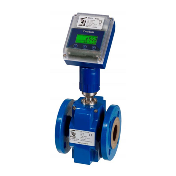
Series FLOMID
Sensor FLOMID-FX
Converter XT5
The art of measuring
R-MI-FIXT5 Rev.: 3 english version
Table of
Contents
Previous
Page
Next
Page
1
2
3
4
5
Advertisement
Table of Contents
Need help?
Do you have a question about the FLOMID Series and is the answer not in the manual?
Ask a question
Questions and answers
Related Manuals for Tecfluid FLOMID Series
Measuring Instruments Tecfluid FLOMID Series Instruction Manual
Sensor and converter (72 pages)
Measuring Instruments Tecfluid FLOMID Series Instruction Manual
Sensor, converter (60 pages)
Accessories Tecfluid FLOMAT Series Instruction Manual
Sensor (40 pages)
Accessories Tecfluid XT5 Instruction Manual
Converter (56 pages)
This manual is also suitable for:
Flomid-fx
Xt5
Table of Contents
Print
Rename the bookmark
Delete bookmark?
Delete from my manuals?
Login
Sign In
OR
Sign in with Facebook
Sign in with Google
Upload manual
Upload from disk
Upload from URL


Need help?
Do you have a question about the FLOMID Series and is the answer not in the manual?
Questions and answers