
Related Manuals for VendNet 3605

Summary of Contents for VendNet 3605
- Page 1 AMBIENT GENERAL MERCHANDISER GLASSFRONT VENDOR SERVICE MANUAL MODELS: 3605 – 5 WIDE 3606 – 6 WIDE MAY 2019 3605 ∙ 3606 ∙ 4225133 Rev C...
- Page 2 3 6 0 5 • 3 6 0 6 4 2 2 5 1 3 3 R e v C...
-
Page 3: Table Of Contents
Table of Contents SAFETY WARNINGS & SPECIFICATIONS ........................ 4 INTRODUCTION ..............................5 GENERAL MERCHANDISER ..........................5 AMERICANS WITH DISABILITIES ACT (ADA) ..................... 5 SERVICING ............................... 5 AT A GLANCE ................................. 6 UNPACKING ................................7 INSTALLATION ............................... 7 REMOVING THE SWING DOOR ........................7 REMOVING THE PULL-OUT DOOR ........................ -
Page 4: Safety Warnings & Specifications
6. This vendor is designed for indoor use and must not be installed in a location where a water hose/jet could be used. DIMENSIONS & WEIGHTS MANUAL REVISION HISTORY TYPE 3605 – 5 Wide 3606 – 6 Wide DATE REASON MODEL... -
Page 5: Introduction
INTRODUCTION This manual contains instructions, service and installation guidelines for the Ambient Glassfront Vendor. Please read this manual thoroughly and follow the instructions. The initial set-up of a vendor is a very important step of insuring that the equipment operates in a trouble-free manner. GENERAL MERCHANDISER The advanced design gives great emphasis to presenting the equipment and the merchandise in the best possible way, using the latest efficient techniques and materials. -
Page 6: At A Glance
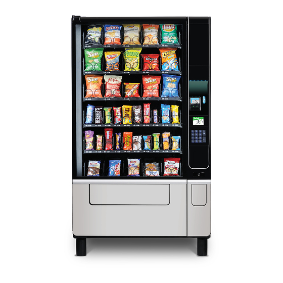
AT A GLANCE PULL-OUT DOOR SWING DOOR DOOR HINGE PLATE BACK-LIT POS CUSTOM GRAPHIC (OPTION) ACCENT DOWN LIGHTING (CHOICE OF COLORS) BILL VALIDATOR MERCHANDISING GLASS SLOT COIN ENTRY BEZEL (LIT) WINDOW KEYPAD/3.5” COLOR DISPLAY 10” CAPACITIVE TOUCH SCREEN CASHLESS PAYMENT SLOT PRODUCT DELIVERY DOOR FLAP COIN RETURN/CHANGE... -
Page 7: Unpacking
UNPACKING This vendor was thoroughly inspected before leaving the factory and the delivering carrier has accepted this vendor as their responsibility. Please note any damage to packaging and/or machine at the time of delivery and report them to the carrier. Request a written inspection report from the claims inspector to file any claim for damage. -
Page 8: Removing The Pull-Out Door
REMOVING THE PULL-OUT DOOR If it proves necessary to reduce the machine depth to approximately 31" the pull-out door can be removed as follows: Remove the (2) stop screws from the top and bottom slider channel as shown in Fig 5. Top Hinge: The Pull-Out Door can now be brought out further to provide better access. - Page 9 REMOVING THE PULL-OUT DOOR . . . Contd. Remove the (4) screws from the top brace as shown in Fig 8 Fig 8. Remove & retain these (4) screws Starting at the bottom, remove and retain the (3) screws from each of the (4) top &...
-
Page 10: Power Cord
POWER CORD Loosen the (4) screws fixing the connection box cover, remove the cover and park on (2) screws as shown in Fig 11. The power cord and GFCI can be removed from its housing, the cover can then be replaced and secured. Keep the power cord secured on the center back of the cabinet until the vendor is placed into its final location to avoid damage to the cord. -
Page 11: Loading Products
LOADING PRODUCTS Load products from front to back making sure all items fit freely between the spiral spaces. Do not attempt to force oversize items or packages into the spiral spaces. Do not skip a space. Place the product on the bottom of the compartment on the product spirals on the tray floor and do not bridge across the spiral. -
Page 12: Spiral Adjustment
SPIRAL ADJUSTMENT The shape, size and thickness of a product affect how well it is ADJUST SPIRAL ADJUST SPIRAL ejected from the tray. Most products can be vended successfully COUNTER CLOCKWISE CLOCKWISE FOR when the spiral end is positioned at 7 or 5 o’clock as shown. If FOR THINNER THICKER PRODUCTS... -
Page 13: Dual Pinion Gear
DUAL PINION GEAR The dual-spiral configuration utilizes a single motor and a pair of pinion gears, the motor pinion gear drives the idle paired gear. The idle pinion gear/spiral adaptor is snapped into its retainer and held in place by the housing as shown below. The pairs of gears/spirals are staggered across the tray, each pair being either in front or behind the adjacent pair. -
Page 14: Door Switch
DUAL PINION GEAR ..Contd. The illustration below shows the adjacent pairs of pinion gears offest rearward/forward The spiral/adaptors and its pinion gears can be meshed together such that the ends of the spirals are mirrored in position to ensure the spirals push the item to be vended evenly and consistently. -
Page 15: Service Mode
SERVICE MODE Use the Service Mode to program and service the vendor. Use the keypad as an input device. Observe the display for information while in Service Mode. SERVICE MODE BUTTON To enter Service Mode, press the Service Mode Button once, it is located in the bottom left hand corner of the control board, see Fig 18. -
Page 16: Installing A Coin Changer
INSTALLING A COIN CHANGER Mount the changer unit onto the 3 screws provided and then secure, See Fig 19. Check the alignment between the underside of coin entry chute and top of entry hopper, adjust chute so there is only 1/8” (3mm) clearance. With the machine switched ON press the coin return button to check the operation of the coin return. -
Page 17: Bill Validator Operation (Optional)
BILL VALIDATOR OPERATION (OPTIONAL) To remove the bills from the Bill Validator push the tab on the top of the bill box and lift up. To clear jams or cleaning unlatch lower unit as shown. Dollar Bill Validator cleaning instructions well more advanced service information can be... -
Page 18: Preventive Maintenance
PREVENTIVE MAINTENANCE CAUTION: Always disconnect power source BEFORE cleaning or servicing. IMPORTANT: To ensure the vendor delivers its maximum appeal and earning potential is should be kept clean and hygienic at all times! WEEKLY CLEAN CABINET EXTERIOR Clean with a mild detergent and water, rinse and dry thoroughly. Plastic exterior parts may be cleaned with a quality plastic cleaner. -
Page 19: Parts Ordering Procedure
If you do not have the right parts manual: contact VendNet™. If you have any questions, check out our Website www.vendnetusa.com or call VendNet. Ask for the Parts Department. We will be happy to assist you. Email: vendnet@vendnetusa.com... -
Page 20: Evoke 5 Electrical Schematic
EVOKE 5 ELECTRICAL SCHEMATIC 3 6 0 5 • 3 6 0 6 4 2 2 5 1 3 3 R e v C... -
Page 21: Evoke 6 Electrical Schematic
EVOKE 6 ELECTRICAL SCHEMATIC 3 6 0 5 • 3 6 0 6 4 2 2 5 1 3 3 R e v C... -
Page 22: Flex Control Board Layout
FLEX CONTROL BOARD LAYOUT I-VEND REFRIGERATION KEYPAD RELAYS SERVICE MODE SW FLEX CONTROLLER 4224664 24VDC 3 6 0 5 • 3 6 0 6 4 2 2 5 1 3 3 R e v C... -
Page 23: Notes
NOTES: 3 6 0 5 • 3 6 0 6 4 2 2 5 1 3 3 R e v C... - Page 24 We reserve the right to modify or improve the designs or specifications of such products at any time without notice. VendNet™ 165 North 10th Street...
Need help?
Do you have a question about the 3605 and is the answer not in the manual?
Questions and answers