Table of Contents
Advertisement
Quick Links
COMMUNICATIONS-APPLIED TECHNOLOGY
11250-14 Roger Bacon Drive
Reston, VA 20190
Voice: 800-229-3925
Support: Techsupport@c-at.com
Revision E
5/2009
Setup and Operating Procedures
™
ICRI-WFM
™
Incident Commanders' Radio Interface
A Rapidly Deployable, Radio Interoperability Solution
MANUFACTURED BY
COMMUNICATIONS-APPLIED TECHNOLOGY CO., INC.
RESTON, VA.
CAGE CODE: 0EEY2
http://www.c-at.com
If you have any questions, please contact:
C-AT TECHNICAL SUPPORT at 800-229-3925 (voice) , 703-471-4428 (fax), or
e-mail to
techsupport@c-at.com
Advertisement
Table of Contents

Related Manuals for COMMUNICATIONS-APPLIED TECHNOLOGY ICRI-WFM


Summary of Contents for COMMUNICATIONS-APPLIED TECHNOLOGY ICRI-WFM
- Page 1 ICRI-WFM ™ Incident Commanders’ Radio Interface A Rapidly Deployable, Radio Interoperability Solution MANUFACTURED BY COMMUNICATIONS-APPLIED TECHNOLOGY CO., INC. RESTON, VA. CAGE CODE: 0EEY2 http://www.c-at.com If you have any questions, please contact: C-AT TECHNICAL SUPPORT at 800-229-3925 (voice) , 703-471-4428 (fax), or e-mail to techsupport@c-at.com...
-
Page 2: Table Of Contents
TABLE OF CONTENTS: THEORY OF OPERATION ....................... 3 INTEROPERABILITY DOS AND DON’TS ................4 PRE-OPERATIONAL ACTIVITIES ..................5 “RAPID DEPLOYMENT” SETUP AND OPERATION OF THE ICRI ........ 6 ICRI ............... 6 ETTING UP THE FOR USE WITH PORTABLE RADIOS INITIAL SET-UP.......................... -
Page 3: Theory Of Operation
THEORY OF OPERATION In simplest terms, the ICRI performs several primary functions: Distributes audio received from one two-way radio to other radios, telephone or recording device connected to the ICRI. Utilizes this same incoming audio to ―key‖ the other radios connected to the ICRI. ... -
Page 4: Interoperability Dos And Don'ts
INTEROPERABILITY DOS AND DON’TS These simple ―universal‖ rules will help to ensure that the part of communications interoperability will work properly. 1. Verify that only one interoperability bridge in the area is using the radio frequencies that you will be using. 2. -
Page 5: Pre-Operational Activities
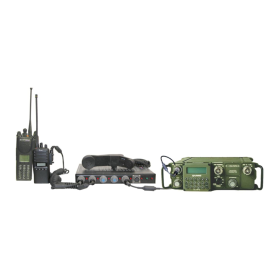
The ICRI‘s internal regulated power supply is both reverse polarity protected, but it is important to check polarity of DC supplies before connecting them to the ICRI. Note: The ICRI power input connector information appears on the bottom of the ICRI. FIGURE 1: ICRI-WFM WITH HANDSET AND RADIOS - 5 -... -
Page 6: Rapid Deployment" Setup And Operation Of The Icri
“RAPID DEPLOYMENT” SETUP AND OPERATION OF THE ICRI Setting up the ICRI for use with portable radios. 1. Place all Talk Group switches in the TG position. 2. After connecting a power source to the ICRI, turn on the ICRI so that power up and input voltage can be verified. -
Page 7: Initial Set-Up
INITIAL SET-UP ICRI Switch View FIGURE 2: FRONT OF ICRI ON-OFF SWITCH: This is a two position switch is used to turn the ICRI ―ON‖ and ―OFF.‖ There is no ―boot‖ time. If the unit is turned off, it will immediately resume all links when turned back on. DC INPUT JACK: This is a 2-pin locking-type jack is the input. -
Page 8: Icri Connector View
ICRI Connector View RADIO INTERFACE JACK (1 thru 5) The five radio interface jacks on this unit are 5 pin, U183 jacks. All radio jacks are compatible with ™ ™ a military and commercial radios and Nextel Direct Connect phones (except Blackberry and i60/i90 models) Pinout: 1- Ground... -
Page 9: Icri Side Views
ICRI Side Views LAND-LINE TELEPHONE/CELL PHONE JACK: This RJ22 locking jack supports the connection of the ICRI to a telephone through the cable of a telephone‘s handset or through a C-AT cable P/N 179.0693 to a cellphone‘s earpiece. SPEAKER PORTS: This is a 3.5mm Tip/Ring miniature ―phono‖connection. -
Page 10: Icri Power
ICRI POWER The following instructions provide four different methods of powering the ICRI. Internal battery 8 ―AA‖ batteries Alternate DC power source (vehicle) AC power Using the internal LiIon battery (Option: May not be enabled) The ICRI will operate on its internal power source for a minimum of 6-8 hours before needing to be recharged. -
Page 11: Using "Aa" Batteries To Power The Icri
Using “AA” batteries to power the ICRI FIGURE 4: BATTERY INSTALLATION (DRAWING) The battery housing is comprised of two parts; the exterior case and an internal tray. NO TOOLS ARE NEEDED TO REMOVE THE TRAY AND REPLACE THE BATTERIES. Connect the adapter‘s plug to the jack labeled DC INPUT. Tighten locking screw, it is important that the connector be firmly seated against the radio so that good electrical contact is made. - Page 12 To reinstall the assembled battery pack onto the adapter, align the slots on the top of the battery pack with the slide rails on the adapter. Slide the battery pack onto the adaptor until it ―locks‖ in place and the edges of the battery pack are aligned with the edges of the adaptor. FIGURE 6: BATTERY ATTACHMENT TO ICRI FIGURE 8: OPTIONAL BATTERY CASE AND FIGURE 7: BATTERY CASE (INTERIOR)
-
Page 13: Using An Alternate Dc Source To Power The Icri
Using an alternate DC source to power the ICRI. When powering the ICRI with an alternate DC source or through vehicle power source, connect the in-line jack to the in-line plug. Note that the pins are polarized and the connection is made so that the jack‘s locking ―blades‖... -
Page 14: Using An Ac Source To Power The Icri
Using an AC source to power the ICRI. This power supply consists of two parts: the three-prong AC power cable and an AC to DC converter with an interconnect cable. Note: The AC supply must not be used where the cables or converter can become wet. Connect the power cord to the converter and to the DC source (110-120V, 60Hz). -
Page 15: Icri Local Handset
Setting up the handset The ICRI-WFM use an H250 compatible handset. To use, plug the handset into the jack labeled ―HANDSET‖. Make sure to properly align the pins of the connector before inserting into the jack. The audio level to the handset speaker can be adjusted by the rotating the volume knob above the jack. -
Page 16: Land Mobile Radio Interface
LAND MOBILE RADIO INTERFACE NOTE: Radio interconnect cables are generally specific to a radio brand and model, although some manufacturer’s use the same connector for several radio models. Interconnect cables provided by C-AT have a seven digit part number label on the cable. Connecting the interface cable to the LMR. -
Page 17: Setting The Radio To Transmit Through The Icri
Setting the radio to transmit through the ICRI Set the audio level on each connected radios to mid-position. NOTE: Some adjustment of volume position may be necessary to clarify radio sound, after mid-position is established. Set the radio to the desired channel. Set the talk group switch Up: Talk Group One Down: Talk Group Two... -
Page 18: Troubleshooting Radio Setup
Troubleshooting radio setup Connect the local handset to the jack on the front of the ICRI labeled, HANDSET. The jack on the handset is similar to those provided for the radio cables. The handset connector contains more pins and is designed to be the only cable used in the HANDSET jack. -
Page 19: Using A Nextel™ Phone In Directconnect™ Mode
Using a Nextel™ phone in DirectConnect™ mode When connecting a Nextel™ connect the phone as you would an L-M-R. Install the radio-end of the ICRI interconnect cable onto the accessory jack at the bottom of the phone, as you would install any accessory (i.e.: a shoulder speaker / microphone). NOTE: At this point, the speaker and mic of the Nextel have been disabled, you will be able to communicate through the handset if both are connected to the ICRI and on the same talk-net. -
Page 20: Icri Phone Link
ICRI PHONE LINK (Option) The ICRI is configured with an RJ22 jack built into the unit. This jack will provide the user the ability connect a standard telephone handset without using the standard telephone port on the front of the ICRI. NOTE: Do not remove the telephone’s handset from its cradle Land-line phone link setup Disconnect the coiled cable from the telephone‘s handset;... -
Page 21: Land-Line Phone Link Setup Using Rj22
2-way radios, the “acoustic coupler” interconnect cable (part number 179.0650) can be used. ICRI-WFM without RJ22 adapter built in may be outfitted with external telephone port to RJ22 dangle. This allows the use of RJ22 adapter and the phone interface as ascribed below. -
Page 22: Using A Cellular Telephone
Using a cellular telephone NOTE: If a cellular telephone with a 2.5mm “headset” jack will be linked through the ICRI to the 2-way radios, an interconnect cable (part number 179.0672) with a 2.5mm plug can be used. When connecting to a cellular telephone connect the small, single shaft connector to the headset jack on the cellular telephone. -
Page 23: Using The Acoustic Coupler
Using the acoustic coupler. The acoustic coupler is installed on a telephone handset or cellular telephone by positioning the transducers over the speaker and microphone of the telephone. Position the BLACK pad directly over the speaker (labeled TO EARPIECE on its cable) and secure by stretching the elastic strap over the handset/cell phone. - Page 24 FIGURE 27: ACOUSTIC COUPLER TO CELLULAR PHONE FIGURE 28: TELELPHONE CONNECTOR ASSEMBLY (DRAWING) - 24 -...
-
Page 25: Appendix A: Icri Options
APPENDIX A: ICRI OPTIONS 250’ Radio Extension Interface (Cable Reel) P/N 179.6214 Positioning one or more of the radios, to be connected to the ICRI at a distance greater than the length of the interface cable may be desirable for one of several operational reasons: 1. - Page 26 Set-up of the cable-reel Equipment required: ICRI, cable-reel, radio interface cable for radio to be placed in the area of poor RF coverage. 1. Connect the cable end that exits from the side of the reel to the radio interface cable. Be sure to align the key-way and secure the connectors together.
-
Page 27: Connecting External Speakers
Connecting External Speakers Connecting the ICRI to external speakers via the optional speaker assembly and cables permits the user to continuously monitor all radio traffic crossing the ICRI. The two separate speaker jacks allow the user to monitor both talk groups simultaneously. To utilize the speaker function, connect the supplied speaker cable to one of the speaker jacks and the input jack of your amplified speaker. -
Page 28: Icri Unit Identifier
ICRI Unit Identifier The ICRI has a ―Unit/Voice ID‖ announcement that sounds every 10 minutes. Each ICRI delivered has a unique ID (for example, ―NJICS Northeast Region Box 201‖). This function will not interrupt any current audio activity, but will wait for activity to cease before sounding. The Unit/Voice ID is also transmitted each time the ICRI is turned on. -
Page 29: Appendix B: Icri Chassis
APPENDIX B: ICRI CHASSIS Set-up Instructions COMMUNICATIONS-APPLIED TECHNOLOGY (C-AT SET-UP INSTRUCTIONS FOR THE ICRI (SEE MANUAL FOR GREATER DETAILS) PATENT #6826647 (U.S.) 1. SELECT THE POWER SOURCE TO BE USED: INTERNAL (RECHARGEABLE BATTERIES) 12V "AA" ALKALINE BATTERY PACK, 115V AC OR VEHICLE SUPPLIED DC. -
Page 30: Connector Pin-Out Data
Connector Pin-out Data FIGURE 33: ICRI PIN OUT DATA - 30 -... -
Page 31: Appendix C: Icri Pictorials
APPENDIX C: ICRI PICTORIALS Applications ICRI-WFM ALTERNATE APPLICATIONS BELOW GRADE OR IN-BUILDING LINK TO TRUNKED REPEATER REPEATER UP TO 5,000' INTERFACE CABLE 1st RESPONDER TALK AROUND INCIDENT TRUNKED CHANNEL CHANNEL LINK COMMANDER REPEATING BODY WIRE SIGNAL BODY WIRE TAPE RECORDER... - Page 32 ICRI-WFM WITH ATTACHMENTS (NOTE: NOT TO SCALE) (+) RED ALLIGATOR CLIPS (-) BLACK 8 "AA" BATTERY PACK UP TO 5,000' INTERFACE CABLE PORTS ARE NOT RADIO SPECIFIC INTERCONNECT CABLE TECHNICAL NOTES ON BOTTOM SIDE. (PORTABLE OR MOBILE RADIO CAN BE USED.) USER INSTRUCTIONS ON TOP COVER.
-
Page 33: Board Adjustments
Board Adjustments - 33 -... - Page 34 - 34 -...
-
Page 35: Appendix D: Fcc 15.21 Information To User
APPENDIX D: FCC 15.21 INFORMATION TO USER: Caution! Change or modification not expressly approved by the party Communications-Applied Technology could void the user‘s authority to operate the equipment. 15.105(b) Information to User: NOTE: This equipment has been tested and found to comply with the limits for a Class B digital device, pursuant to part 15 of the FCC Rules.
Need help?
Do you have a question about the ICRI-WFM and is the answer not in the manual?
Questions and answers