Table of Contents
Advertisement
Quick Links
COMMUNICATIONS-APPLIED TECHNOLOGY
11250-14 Roger Bacon Drive
Reston, VA 20190
Voice: 800-229-3925
Support: Techsupport@c-at.com
Revision I
10/2010
Setup and Operating Procedures
ICRI-E
Incident Commanders' Radio Interface
™
A Rapidly Deployable, Radio Interoperability Solution
Waterproof, Gross Decon-able
MANUFACTURED BY
COMMUNICATIONS-APPLIED TECHNOLOGY CO., INC.
RESTON, VA.
CAGE CODE: 0EEY2
http://
www.c-at.com
If you have any questions, please contact:
C-AT TECHNICAL SUPPORT at 800-229-3925 (voice) , 703-471-4428 (fax), or
e-mail to
techsupport@c-at.com
Advertisement
Table of Contents

Related Manuals for COMMUNICATIONS-APPLIED TECHNOLOGY ICRI-E


Summary of Contents for COMMUNICATIONS-APPLIED TECHNOLOGY ICRI-E
- Page 1 ICRI-E Incident Commanders’ Radio Interface ™ A Rapidly Deployable, Radio Interoperability Solution Waterproof, Gross Decon-able MANUFACTURED BY COMMUNICATIONS-APPLIED TECHNOLOGY CO., INC. RESTON, VA. CAGE CODE: 0EEY2 http:// www.c-at.com If you have any questions, please contact: C-AT TECHNICAL SUPPORT at 800-229-3925 (voice) , 703-471-4428 (fax), or e-mail to techsupport@c-at.com...
-
Page 2: Table Of Contents
APPENDIX B: CONNECTOR PIN-OUT DATA ..............23 APPENDIX C: ICRI APPLICATIONS ..................24 APPENDIX D: ICRI CHASSIS ....................26 APPENDIX E: PART NUMBERS FOR ICRI-E ACCESSORIES AND CABLES ..... 27 APPENDIX F: ICRI BOARD ADJUSTMENTS ..............28 APPENDIX G: FCC 15.21 INFORMATION TO USER: ............30... -
Page 3: Theory Of Operation
Theory of Operation In simplest terms, the ICRI performs two primary functions: Distributes audio received from one two-way radio to other radios, telephone or recording device connected to the ICRI. Utilizes this same incoming audio to ―key‖ the other radios connected to the ICRI. This configuration of the ICRI is designed to be quickly set-up, and to operate for extended periods without additional power sources or specialized support equipment. -
Page 4: Pre-Operational Activities
Pre-Operational Activities Some pre-planning is necessary to ready the ICRI for use. The following should be accounted for before placing the ICRI on-line: Predetermine what the power source will be for the ICRI and verify that the cable or battery pack is available. -
Page 5: Set-Up And Use Instructions
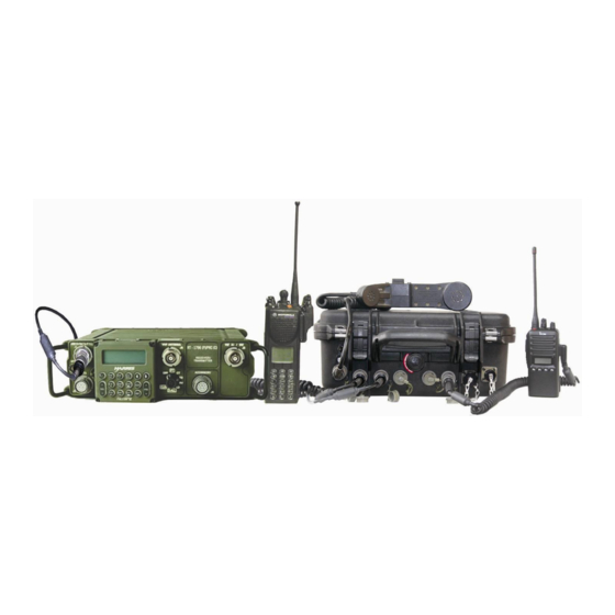
Set-up and Use Instructions The ICRI-E is internally housed in the Pelican case; therefore this version does not provide a location for storing cables and radios inside the unit. However, the ―AA‖ batteries are stored and operational from within the unit and accessible from the front panel. -
Page 6: Operation Of The Icri
Operation of the ICRI Setting up the ICRI for use. Verify ―fresh‖ AA batteries are installed or connect a power source to the ICRI. Turn on the ICRI so that power up and input voltage can be verified. If you need to use a DC source voltage between 6.5 and 7.4 volts, then neither the OK nor the LOW voltage LEDs will be lit, but the ICRI will be working. -
Page 7: Internal Panel
INTERNAL PANEL: FIGURE 3: INTERNAL PANEL ACTIVE VOX (VOICE ACTIVATED CIRCUIT) LED INDICATOR: Each LED is associated with a voice communications port (radio, telephone). When the port receives audio from the radio or other connected device, the LED will light as the audio is received at the ICRI circuitry. -
Page 8: External Pelican Case
OK/ LOW IMPUT VOLTAGE LEDs: These two LEDs indicate the following: The Green LED indicates the input voltage 8.6 or greater. If battery power option is used, the ICRI will have approximately 24 hours of run time at full duty cycle. The red LED indicates the input voltage is 7.5 to 8.5 volts. - Page 9 HANDSET/HEADSET JACK This 5 pin U183 connector supports the H250/H350 handset Pinout: 1- Ground 2- Mic 3- PTT 4- Audio Hi+ 5- Audio Hi- - 9 -...
- Page 10 RADIO JACK (1 thru 5) The five radio interface jacks on this unit are a 5-pin, U183 locking jacks. All radio jacks are ™ ™ compatible with a military and commercial radios and Nextel Direct Connect phones (except Blackberry and i60/i90 models) Pinout: 1- Ground 2- Audio from radio...
-
Page 11: Icri Power
ICRI Power The ICRI-E can be powered by 8 ―AA‖ batteries housed on the inside cover of the unit, external DC or AC power. To power the ICRI 8 “AA” batteries: The battery housing is comprised of two parts; the cover and an internal tray. -
Page 12: Use An Alternate Dc Source To Power The Icri
Use an alternate DC source to power the ICRI. When powering the ICRI with an alternate DC source or through vehicle power source, connect the in-line jack to the in-line plug. Note that the pins are polarized and the connection is made so that the jack’s locking ―blades‖... -
Page 13: Use An Ac Source To Power The Icri
Use an AC source to power the ICRI. This power supply consists of two parts: the three-prong AC power cable and an AC to DC converter with an interconnect cable. Note: The AC supply must not be used where the cables or converter can become wet. Connect the power cord to the converter and to the DC source (110-120V, 60Hz). -
Page 14: Land Mobile Interface
Land Mobile Interface NOTE: Radio interconnect cables are generally specific to a radio brand and model, although some manufacturers use the same connector for several radio models. Interconnect cables provided by C- AT have a seven digit part number label on the cable. Connect Interface cables Install the radio-end of the ICRI interconnect cable onto the radio, as you would install any radio accessory (i.e.: a shoulder speaker / microphone). -
Page 15: Set The Radio To Transmit Through The Icri
Set the radio to transmit through the ICRI Set the audio level on each connected radios to mid position. NOTE: Radio interconnect cables are generally specific to a radio brand and model, although Set the radio to the desired channel. Set the talk group switch Up: Talk Group One Down: Talk Group Two... -
Page 16: Optional Satphone, Land-Line Telephone, Cellular Phone Interface
The ICRI can be configured with an optional RJ-10 jack adapter that attaches to the 8-pin jack on the outside of the ICRI-E. This jack will provide the user the ability connect a standard telephone handset without using the standard telephone port on the front of the ICRI. -
Page 17: Nextel Tm Phone In Direct Connect Tm Mode
NOTE: Third party needs to be aware of basic radio etiquette and delays for radio keying Otherwise, they will monopolize the radio channel or will not be properly understood by the radio users. To remove the connector for cable storage, push inward on the locking ring and turn the ring counter clockwise to release the locking mechanism. -
Page 18: Appendix A: 250' Radio Extension Cable Reel
APPENDIX A: 250’ Radio Extension Cable Reel Positioning one or more of the radios, to be connected to the ICRI at a distance greater than the length of the interface cable may be desirable for one of several operational reasons: 1. -
Page 19: Set-Up Of The Cable-Reel
Set-up of the cable-reel Equipment required: ICRI, cable-reel, radio interface cable for radio to be placed in the area of poor RF coverage. 1. Connect the cable end that exits from the side of the reel to the radio interface cable. Be sure to align the key-way and secure the connectors together. - Page 20 Set-up of the cable-reel with reversal cables: Attach one end of cable ―A‖ to the male connector located near the center hub on the reel. Attach the other end of cable ―A‖ to an ICRI radio port. Attach one end of adapter ―B‖ to the female connector at the ―free‖ end of the cable. Attach the other end of adapter ―B‖...
- Page 21 - 21 -...
- Page 22 - 22 -...
-
Page 23: Appendix B: Connector Pin-Out Data
APPENDIX B: Connector Pin-out Data IMPORTANT! TO ICRI ALL CONNECTOR INFORMATION VIEWED FROM THIS POINT (WIRED SIDE). POWER CONNECTOR HANDSET INTERFACE RADIO INTERFACE TELEPHONE/ACOUSTIC COUPLER B- GND(-) A- POWER(+) A- TO PHONE A- GND A- GND B- FROM PHONE B- AUDIO FROM RADIO B- AUDIO FROM RADIO C- TO PHONE C- P-T-T... -
Page 24: Appendix C: Icri Applications
APPENDIX C: ICRI Applications TAPE RECORDER MOBILE VEHICLE-MOUNT RADIO BODY WIRE RECEIVER FIGURE 18: REPEATING BODY WIRE SIGNAL INTERFACE CABLE TRUNKING SYSTEM UP TO 5,000' TOWER TALK AROUND TALK AROUND TRUNKED RADIO TRUNKED RADIO INCIDENT COMMANDER FIGURE 19: BELOW GRADE OR IN-BUILDING LINK TO TRUNKED REPEATER - 24 -... - Page 25 C OM MU NICA TION S- AP PL IE D TE CH NOLOGY C AGE CODE : 0EEY2 P/N : 179.*** AC POWER SUPPLY ALIGATOR CLIPS BLACK CIGARETTE LIGHTER 8 "AA" BATTERY PACK UP TO 5,000' INTERFACE CABLE FIGURE 20: ICRI-E WITH ATTACHMENTS (NOT TO SCALE) - 25 -...
-
Page 26: Appendix D: Icri Chassis
APPENDIX D: ICRI Chassis FIGURE 21: TOP COVER OF THE ICRI - 26 -... -
Page 27: Appendix E: Part Numbers For Icri-E Accessories And Cables
APPENDIX E: Part Numbers for ICRI-E Accessories and Cables NOTE: Please contact C-AT if you require an interface cable for a radio not listed or for current pricing and options POWER OPTIONS 115V AC adaptor (in-line switching power supply) 320.0446 24VDC power cable, 10’... -
Page 28: Appendix F: Icri Board Adjustments
APPENDIX F: ICRI Board Adjustments - 28 -... - Page 29 - 29 -...
-
Page 30: Appendix G: Fcc 15.21 Information To User
APPENDIX G: FCC 15.21 Information to User: Caution! Change or modification not expressly approved by the party Communications-Applied Technology could void the user’s authority to operate the equipment. 15.105(b) Information to User: NOTE: This equipment has been tested and found to comply with the limits for a Class B digital device, pursuant to part 15 of the FCC Rules.
Need help?
Do you have a question about the ICRI-E and is the answer not in the manual?
Questions and answers