Table of Contents
Advertisement
Quick Links
Advertisement
Table of Contents

Subscribe to Our Youtube Channel
Related Manuals for FunkTronic Major BOS V Series


Summary of Contents for FunkTronic Major BOS V Series
- Page 1 Major BOS V(oIP) Major BOS 4V Major BOS 1V Major BOS 8V...
-
Page 2: Table Of Contents
Contents Connectivity Major BOS 1V/4V/8V Control and Display Elements Layout - Major BOS 4V Layout - Major BOS 8V Calling Radio Channels Encoder Transmitter Control Connection to Telephone AF Microphone Selection Opto-Coupler Input Functions for TETRA Digital Radios Configuration via the Web Interface The Web Interface The System Pages The Application Pages... -
Page 3: Connectivity
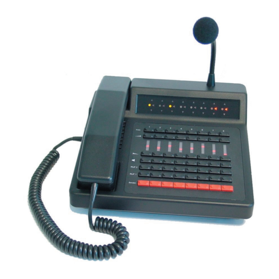
Major BOS 1V/4V/8V Major BOS 1V, Major BOS 4V and Major BOS 8V are µC-controlled desktop controller units for 2-way radio systems controlling one, up to four or eight radios, respectively. The connection to the radios is achieved over one single ethernet connection (LAN or via Internet) instead of separate cables for each radio circuit. -
Page 4: Control And Display Elements
Control and Display Elements Keyboard The keyboard holds the following functions for each of the four/eight channels: Button Function (standard) (Funk-)kreis x selection button VOL+ increase volume VOL- decrease volume mute loudspeaker special function (not assigned, only MBOS 4V) I / RUF1 button for tone call 1 II / RUF2 button for tone call 2... -
Page 5: Layout - Major Bos 4V
Layout - Major BOS 4V 1 - Transmiting- , Squelch- , Selection Status LED 2 - Channel Selection Buttons 3 - Volume Display (row of LEDs) 4 - Volume Control Buttons (+/-) 5 - Loudspeaker Buttons (mute) 6 - Special Function Buttons 7 - Encoder Buttons (I/II) 8 - PTT (for gooseneck or headset microphone) 9 - Loudspeaker... -
Page 6: Layout - Major Bos 8V
Layout - Major BOS 8V , carrier , loudspeaker and selection displays selection buttons volume buttons (increase) volume displays (LED line) volume buttons (decrease) loudspeaker buttons (mute) call 1 buttons call 2 buttons PTT buttons (for gooseneck microphone) loudspeaker handset with PTT button gooseneck microphone mbosv_eng (25.02.2014) - 6 -... -
Page 7: Calling Radio Channels
Calling Radio Channels Channel Selection To activate one of the different channels push the corresponding selection button. To deactivate a channel again push the corresponding selection button once more. Depending on the configuration (see also: Configuration via the Web Interface) you can either select several channels simultaneously or only one channel at a time. -
Page 8: Encoder
Encoder Major BOS V has an integrated encoder for call 1 and call 2. The calls for each channel are transmitted directly with the corresponding buttons on the keyboard (I / RUF 1 or I / RUF 2). The calls are transmitted as long as the corresponding button is being pressed. Transmitter Control The transmitters of the selected radio channels are activated with one of the PTT but- tons (e.g. -
Page 9: Opto-Coupler Input
Opto-Coupler Input The opto-coupler input on ST5 can be configured via Web interface to fulfill different tasks in the same way as all inputs can be. To activate the opto-coupler input, a direct current (3V < U < 15V) is necessary that can be obtained directly from ST14a/2. -
Page 10: Configuration Via The Web Interface
Configuration via the Web Interface Preparing the PC To be able to acces the Web Interface of the Major BOS V, a PC has to be configured properly. Ex factory, the network address of the Major is as follows: IP address: 192.168.16.181 Subnet mask: 255.255.255.0... -
Page 11: The Web Interface
This kind of problems can be completely avoided if Major and PC are connected to a to a separate network hub or switch, which is solely used for that purpose. Example Configurations of Funktronic devices in different network architectures can be found in the manual: "Ethernet Connections". -
Page 12: The System Pages
The System Pages After entering the Major's IP address into the adress bar of the browser, system page 1 is displayed (see image above). This page contains the local network settings of the Major BOS V. Als Startseite wird die System-Seite 1 geöffnet (siehe oben). In order to have effect, any configuration changes need to be confirmed with "Anwenden". - Page 13 Netzmaske Subnet mask, as is used in the local network. Default: „255.255.255.0“ Gateway IP-Adresse The address of the router/DSL gateway in the local network. This is necessary, if the remote stations are not part of the same network. Default: „0.0.0.0“ Primärer DNS-Server A DNS server is only necessary if host/DNS names are used.
-
Page 14: The Application Pages
Ziel IP Adresse The IP addresses of the remote stations must all be different (also different from the own IP address). Port für Audio/NF The audio port is used for transmission of the audio packets. The used UDP protocol must be activated in firewalls. - Page 15 Funktion der Eingänge / Funktion der Ausgänge The possible functions of inputs and outputs can be freely assigned to the respective pins. For PTT inputs, the assignment to the desired microphones is also made here. Eingangsverstärkung / Ausgangsverstärkung If necessary, the different AF input and output levels can be adjusted here. Mikrofonausgabepegel / Ausgabepegel Ruf The output levels of the microphone and of call 1/2 can also be adjusted separately for the different AF directions.
- Page 16 Max. Lautstärke Hörer on Hook Highest volume level, if the handset is hung up. Max. Lautstärke Hörer off Hook Highest volume level, if the handset is taken. Max. Lautstärke Sender an Highest volume level, if the transmitter is active. Max. Lautstärke Sender eigener Kreis an Highest volume level, if the transmitter of the own is active.
-
Page 17: Rs232 Monitor
RS232 Monitor For via the RS232 interface the respective socket of the Major needs to be connected to the PC's COM port. In case your PC does not have a COM socket, you can also use a COM-USB converter. In order to read the syslog messages, you need to use a terminal software (e.g. -
Page 18: Sockets Pinout
Sockets Pinout All sockets of the Major shown from rear view. Layout Power Two connectors for headsets are available. A headset can be connected to ST14. An external PTT button (e.g. foot switch) can be connected to ST14A. 12 VDC, max 1,5 A, inside: + , outside: GND Layout HS Headset Layout TB Tape... -
Page 19: Technical Data
Technical Data Supply Voltage +12V -15% +25% Current Consumption ca. 160-400 mA Input Level (S/E) Factory setting 775 mV (= 0 dB) / 600Ohm Adjustment range -99 dB to +26 dB Input impedance 600 Ohm Output Level (S/E) Factory setting 500 mV (= - 3,8 dB) / 200 Ohm Adjustment range -99 dB to +26 dB / 200 Ohm... -
Page 20: General Safety Remarks
November 2005, the purchasers or users are obliged to return old equipment produced by us free of cost. FunkTronic GmbH will dispose of this old equipment at its own expense according to regulations. - Page 21 Release Notes 25.02.2014 - first English version of the manual mbosv_eng (25.02.2014) - 21 -...
Need help?
Do you have a question about the Major BOS V Series and is the answer not in the manual?
Questions and answers