Table of Contents
Advertisement
Quick Links
Advertisement
Table of Contents

Related Manuals for FunkTronic Major BOS 8a


Summary of Contents for FunkTronic Major BOS 8a
- Page 1 Major BOS 8a...
-
Page 2: Table Of Contents
Inhalt Page Major BOS 8a Connectivity Control and Display Elements Major BOS 8a Calling a Single Radio Subscriber RX-AF Outputs Encoder External Signalling Device Transmitter Control Connection to Telephone AF Microphone Selection Channel Selection (additionally) Opto-Coupler Input Connecting several Major in Parallel Circuit... -
Page 3: Major Bos 8A
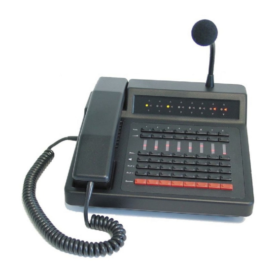
Major BOS 8a Major BOS 8a is a µC-controlled desktop controller unit for 2-way radio systems controlling up to eight radios. Different operating parameters can either be factory preset or programmed during installation. Connectivity For operation 12 V DC power supply is necessary. Up to eight channels (radio sets, PA systems -/intercom etc.) can be connected, also an external handset/headset, up to two... -
Page 4: Control And Display Elements Major Bos 8A
Control and Display Elements Major BOS 8a , carrier , loudspeaker and selection displays selection buttons volume buttons (increase) volume displays (LED line) volume buttons (decrease) loudspeaker buttons (mute) call 1 buttons call 2 buttons PTT buttons (for gooseneck microphone) - Page 5 Control and Display Elements (continued) Keyboard The keyboard holds the following functions for each of the eight channels: Kreis selection button increase volume decrease volume mute loudspeaker Ruf 1 button for tone call 1 Ruf 2 button for tone call 2 Senden PTT button Carrier Display (Squelch)
-
Page 6: Calling A Single Radio Subscriber
1 = only one channel at a time selected When channels are activated the channel selection LED lights up. If the channel has already been selected by a different Major BOS 8a the device can be programmed so that the corresponding channel selection LED flashes. - Page 7 (see section Parallel circuit of several Major BOS 8a). In EEPROM register 025 the loudspeaker switching statuses of the radio channels 1..8 (bit 0..7) can be preselected after turning on the radio installation.
- Page 8 Loudspeaker (continued) The EEPROM-Register 02A in bit 0 can be configurated so that the receiver AF of all radio channels (without muting) is switched to the loudspeaker or that the corresponding radio channels also have to be activated additionally. register 02A receiver AF on loudspeaker bit 0: 0 = all radio channels without muting...
- Page 9 Earphones The receiver AF of the selected radio channel can always be heard on the earphones of the handset and the headset. The earphone AF of individual radio channels can be muted either manually by pressing the selection buttons or automatically by transmitting on the active or on one of the other radio channels (earphone muting).
-
Page 10: Rx-Af Outputs
The volume-controlled receiver AF can be tapped individually for each radio channel on the Major BOS 8a. The outputs can be used e.g. for connecting external AF-amplifier. The receiver AF (RX-AF outputs) of individual radio channels can be muted either... -
Page 11: External Signalling Device
- the PTT2 input can be programmed as headset detection (programming register 04C) - the Major BOS 8a can detect if a headset is connected by measuring the headset supply voltage (programming register 051/052). The threshold level in register 051 has to be set so that the measured supply voltage (at ST10 between Pin 2 and 5) without headset is higher and with headset is lower than the threshold level. -
Page 12: Opto-Coupler Input
Opto-Coupler Input The Major BOS 8a has an opto-coupler input at connector ST14a. This opto-coupler input can be programmed with different functions. a) If this register is encoded to value ´00´, the opto-coupler input switches the handset/ headset to the audio-frequency-connection when activated (standard function, see section Connection to Telephone AF). -
Page 13: Connecting Several Major In Parallel Circuit
Connecting several Major in Parallel Circuit As the AF outputs are only open during transmission and the AF inputs can be switched to high-resistance by pulling the jumpers J1 to J4, it is possible to connect several Major BOS 8a in parallel. Therefor, all connections to the single radio circuits (TX-AF, RX-AF, squelch and transmitter PTT) have to be connected in parallel (bus- or hub-wiring). -
Page 14: Actions On Detection Of Busy Lines
8 as blinking channel selection LED / TX LED (0/1) You can also configure how the Major BOS 8a treats busy radio channels: e.g. the trans- mitter PTT can be disabled and/or the receiver-AF for the loudspeaker (and the RX-AF... -
Page 15: Monitoring-Interface Tbbox4 (Accessories)
Major BOS 4a by the I²C-Bus (connector ST14). If the evaluation status is to be transmitted to several Major BOS 8a or controlling the tape relay of the TBBox4 is used by several Major, their control inputs have to be connected to the I²C-Bus-concentrator I2C-Con. - Page 16 Universal-encoder/decoder-module UGA00. The status of the switching outputs DEC1 and DEC2 of all UGA-modules is transmitted to the Major BOS 8a and causes the loudspeaker-AF of the corresponding radio channels to be turned on(if it was turned off before): a) If the switching output DEC2 is turned on because of the UGA-decoding, then the loudspeaker-AF of the corresponding radio channel is turned on permanently.
-
Page 17: Tape Control (Continued)
Tape Control (continued) register 03A audio tape switching contact TBBox4(2) controlled by bit 0: circuit 1 NO/YES (0/1) bit 1: circuit 2 NO/YES (0/1) circuit 3 NO/YES (0/1) bit 2: circuit 4 NO/YES (0/1) bit 3: circuit 5 NO/YES (0/1) bit 4: circuit 6 NO/YES (0/1) bit 5:... -
Page 18: Switching Matrix For Circuit Forwarding (Optional)
Programming Example: radio circuits 1-6: analogue, radio circuit: 7-8 digital Only the circuit of the current conversation is to be heard on the loudspeaker register 020: C0 register 021: 00 register 054: C0 The values to program in all 3 registers are calculated as follows: circuit 1: 1 circuit 2: 2 circuit 3: 4... -
Page 19: New Registers In Mbos 8A
Starting with software version V3.8 of the Major BOS 8 main board forwarding to certain circuits can also be activated and deactivated via the RS232 interface. Therefor, there is the new command '$Kxx'. xx (00-FF) corresponds to the active circuits as also programmable in registers 080-087 Ab Software Version V3.8 der Major BOS 8 Hauptplatine lassen sich die Überleitkreise auch durch die RS232 aktivieren und deaktivieren. -
Page 20: Service Program
<$A2><CR>(=Enter). Then the monitor menu ( see above) appears on the screen. If the Major BOS 8a is to be programmed or controlled automatically by a PC or a control center computer it may be useful for the monitor function to be immediately available when turned on (monitor status = ´01`or ´02`). - Page 21 The monitor status can be programmed in EEPROM register 026 as follows: register 026 Monitor status after turning on 00 = monitor function is turned off 01 = special control function (WED) is turned on 02 = monitor function is turned on The monitor status (´00`,´01`or ´02`) can also be switched over while operating by entering <$A0><CR>, <$A1><CR>...
-
Page 22: Eeprom Adresses
EEPROM Adresses register programming for volume after power-on circuit 1 circuit 2 circuit 3 circuit 4 circuit 5 circuit 6 circuit 7 circuit 8 RX-AF output (while transmitting on own circuit) for circuit 1 OFF/ON (0/1) bit 0: circuit 2 OFF/ON (0/1) bit 1: bit 7: circuit 8 OFF/ON (0/1) -
Page 23: Eeprom Adresses (Continued)
EEPROM Adresses (continued) register programming for loudspeaker status after power-on bit 0: circuit 1 OFF/ON (0/1) bit 1: circuit 2 OFF/ON (0/1) bit 7: circuit 8 OFF/ON (0/1) monitor status after power-on 00 = monitor function is turned on 01 = special control function (WED) is turned on 02 = monitor function is turned on save selected circuits NO/YES (00/01) save loudspeaker statusses NO/YES (00/01) - Page 24 EEPROM Adresses (continued) register programming for PTT keying blocked if circuit is busy bit 0: circuit 1 NO/YES (0/1) bit 1: circuit 2 NO/YES (0/1) bit 7: circuit 8 NO/YES (0/1) loudspeaker AF is muted if circuit is busy bit 0: circuit 1 NO/YES (0/1) circuit 2 NO/YES (0/1) bit 1:...
- Page 25 EEPROM-Adresses (continued) register programming for loudspeaker is on for n * 1sec at DEC1 for circuit 1 circuit 2 circuit 3 circuit 4 circuit 5 circuit 6 circuit 7 circuit 8 button that is simulated via INP1 on MBOS8a button that is simulated via INP1 on MBOS8a opto-coupler input digit 1 assignment to...
- Page 26 EEPROM Adresses (continued) register programming for headset detection with PTT2 input at headset socket (ST10) PTT2 active ==> headset microphone in use PTT2 off ==> gooseneck microphone in use 00 = normal PTT function, PTT2 is headset PTT > 00 = PTT2 is headset detection, SH-micro is open, HS-micro is active >00 = INP 1-3 and opto-coupler is SH/HS-PTT (if programmed)
- Page 27 EEPROM-Adressen (continued) register programming for selection analogue or digital radio (SW V5.2 or newer) 0 = analogous radio, 1 = digital radio bit 0 - 3: radio 1 bis 4 bit 4 - 7: radio 5 bis 8 predefined circuits to which forwarding is active upon long pressing of the loudspeaker button of the respective circuit BIT0 = circuit 1 ..
-
Page 28: Jumpers Und Potentiometers
Jumpers und Potentiometers If necessary different configurations and adjustments can be made by using several jumpers and potentiometers. See Layout. The jumper functions can be seen in the following chart: Jumper Function RX-AF input circuit 1 is 600ohm/3kohm (1/2) RX-AF input circuit 2 is 600ohm/3kohm (1/2) RX-AF input circuit 3 is 600ohm/3kohm (1/2) -
Page 29: Board Layout
Board Layout mbos8a_eng (13.03.2014) - 29 - Kompetent für Elektroniksysteme... -
Page 30: Adjustment Instructions
Adjustment Instructions The AF levels have already been correctly preadjusted ex factory. If necessary please follow these instructions. Adjustment RX inputs (radio channels 1..8) (receiving radio) At the RX-input radio channel 1 ( and 2-8) feed in the AF level provided by the radio device at 1000 Hz. -
Page 31: Sockets Pinout
Sockets Pinout ST12 ST10 ST14A ST14 All sockets of the Major shown from rear view. Two connectors for headsets are available. A headset Layout FK 1- 8 (radio channels) can be connected to ST14. An external PTT button (e.g. ST1 - 8 foot switch) can be connected to ST14A. - Page 32 Sockets Pinout (continued) Socket ST15 for ext. RX-AF amplifier (internal 26-pin latch socket) RX-AF output circuit 1 LS1 (loudspeaker AF) RX-AF output circuit 2 LS2 (loudspeaker AF) RX-AF output circuit 3 LS3 (loudspeaker AF) RX-AF output circuit 4 LS4 (loudspeaker AF) RX-AF output circuit 5 LS5 (loudspeaker AF) RX-AF output circuit 6 LS6 (loudspeaker AF) RX-AF output circuit 7 LS7 (loudspeaker AF)
-
Page 33: Technical Data
Technical Data Supply voltage +12V -15% +25% current consumption typ. 350 mA (max. 650 mA) Input level (RX in), (from circuit 1..8) factory settings 775 mV (= 0 dBm) / 600 ohm 500 mV (= -3,8 dBm) / 200 ohm adjustment range (with poti P12..P19) - 8 dBm to +3 dBm input impedance... -
Page 34: General Safety Remarks
November 2005, the purchasers or users are obliged to return old equipment produced by us free of cost. FunkTronic GmbH will dispose of this old equipment at its own expense according to regulations. -
Page 35: Release Notes
Release Notes 10.09.2012 - first English version of Major BOS 8a manual released 25.02.2014 - pinout of socket ST14 revised 13.03.2014 - order information (RS232 cable) added mbos8a_eng (13.03.2014) - 35 - Kompetent für Elektroniksysteme... -
Page 36: Appendix
Appendix Conversion chart: hexadecimal (HEX) <--> decimal (DEC) The corresponding HEX number (2 digits, HEX numbers are often indicated by a preceding '$' sign) to a common DEC number (<256) or vice versa can be directly deduced from this table: HEX $x0 $x1 $x2 $x3 $x4 $x5 $x6 $x7 $x8 $x9 $xA $xB $xC $xD $xE $xF 100 101 102 103 104 105 106 107 108 109 110 111 112 113 114 115 116 117 118 119 120 121 122 123 124 125 126 127...
Need help?
Do you have a question about the Major BOS 8a and is the answer not in the manual?
Questions and answers