Table of Contents
Advertisement
Quick Links
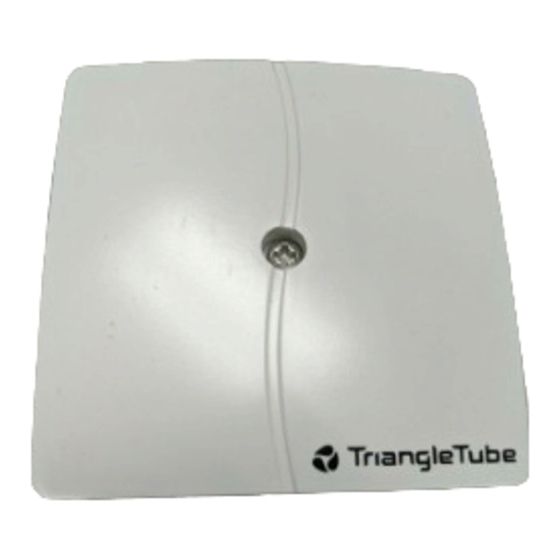
Outdoor Sensor - PSSENS01
Fig. 1: Sensor Enclosure and Components
Mounting the Outdoor Sensor
1. Remove the front cover and mounting screws /
anchors from the sensor enclosure.
2. When mounting the enclosure, the exterior wall
selected should represent the heat load of the
building. Typically a northern or northeastern
wall will suit most buildings. A southern facing
wall for those buildings, which may have large
glass walls or windows on the southern face.
3. Ensure the sensor enclosure is shielded from
direct sunlight or the effects of heat or cold
from other sources (exhaust fans, appliance
vents...) to prevent false temperature sensing.
4. Mount the sensor enclosure at an elevation on
the exterior wall to prevent accidental damage
or tampering.
5. Avoid mounting the enclosure in areas subject-
ed to excessive moisture.
6. Once an area on the exterior wall has been
determined, to affix the enclosure use the enclo-
sure as a template to mark the location of the
mounting screws.
7. Using a 3/16" drill bit, drill 2 pilot holes on the
marked locations.
8. Tap the enclosed plastic anchors into the pilot
holes. Use care not to damage the anchors.
9. Mount the sensor enclosure using the screws
provided.
(2) Plastic Anchors
Sensor Enclosure
(2) Mounting
Seal Gasket
Wiring the Sensor
1. Remove the sealing nut and sealing gasket from
the sensor enclosure.
2. Route 18 AWG 2-wire cable or similar wire
cable through the sealing nut and gasket.
Connect the wire ends to the sensor terminals 1
and 2.
2a. Cut a small slit in the seal gasket and route 18
AWG 2-wire cable or similar wire cable
through the seal gasket into the enclosure.
3. Re-insert the sealing gasket and tighten the seal-
ing nut to the sensor enclosure.
4. Route the sensor cable back to the appliance,
ensuring the cable is not route parallel to tele-
phone or power cables.
NOTI E
If the sensor cable is located in an area with
sources of potential electromagnetic interfer-
ence (EMI) the sensor cable should be shield-
ed or the wires should be routed in a ground-
ed metal conduit. If using shielded cable the
shield wire should be connected to the com-
mon ground of the unit.
5. Connect the sensor cable to the outdoor sensor
terminals on the 24V terminal strip located
inside the appliance enclosure (see appliance
wiring diagram).
1
Screws
Front Cover
Advertisement
Table of Contents

Related Manuals for TriangleTube PSSENS01

Summary of Contents for TriangleTube PSSENS01
- Page 1 Outdoor Sensor - PSSENS01 (2) Plastic Anchors Sensor Enclosure (2) Mounting Seal Gasket Screws Fig. 1: Sensor Enclosure and Components Front Cover Mounting the Outdoor Sensor Wiring the Sensor 1. Remove the front cover and mounting screws / 1. Remove the sealing nut and sealing gasket from anchors from the sensor enclosure.
- Page 2 Outdoor Sensor - PSSENS01 NOTI E The following section applies to PRESTIGE using the Honeywell Type 5 MCBA Control. This Control is identified as Honeywell MCBA 54201.
- Page 3 Outdoor Sensor - PSSENS01 Summer / Winter Switch CH Reset Curve Coldest Day (Parameter 11) If required the CH (Central Heating) system can be turned off at the appliance, similar to manual sum- mer / winter switch by press/hold the “+” button the “StbY...
- Page 4 Outdoor Sensor - PSSENS01 Entering MCBA Access Code NOTI E The installer must enter the MCBA Access Code to adjust the advanced parameter settings of the The actual parameter values displayed on the MCBA. The Access Code can be entered as follows: display may vary depending on the application, 1.
- Page 5 Outdoor Sensor - PSSENS01 Parameter 4 Set Point Parameter 10 Set Point Outdoor Air Temperature ( F) Graph 1: Outdoor Air Temperature Reset Curve (Example) Table 1: Outdoor Air Temperature Reset (Example) Graph 1 illustrates Parameter 4 adjusted to 140ºF target temperature at 0ºF outdoor air temperature.
- Page 6 Outdoor Sensor - PSSENS01 NOTI E The following section applies to the CHALLENGER condensing boiler and It’s internal control module.
- Page 7 Outdoor Sensor - PSSENS01 Adjusting Outdoor Reset Curve CH Reset Curve Warmest Day The appliance CH set point along with Parameters (Parameter 7) 5, 6 & 7 define the settings of the outdoor reset curve. See Graph 2 and Table 2, page 8 for an...
- Page 8 Outdoor Sensor - PSSENS01 CH Set Point Parameter 5 Set Point Outdoor Air Temperature ( F) Graph 2: Outdoor Air Temperature Reset Curve (Example) Table 2: Outdoor Air Temperature Reset (Example) Outdoor CH target Temp. 10ºF or Lower 140ºF 30ºF 117ºF 50ºF...
Need help?
Do you have a question about the PSSENS01 and is the answer not in the manual?
Questions and answers